Clause 3 – How to understand the definition of “protective impedance”
protective impedance: impedance connected between live parts and accessible conductive parts of class II constructions so that the current, in normal use and under likely fault conditions in the appliance, is limited to a safe value.
Case 1:
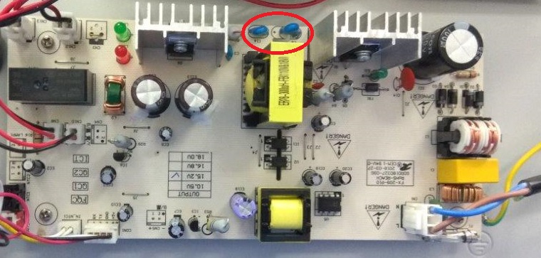
The first case is usually some situations that require low-voltage power supply, such as adapter-powered products. The output voltage of the adapter is DC12V, DC24V or DC5V. These low-voltage parts can generally be touched by users because the DC low-voltage part is obtained by transformer transformation and rectification of the rectifier current. Therefore, it is necessary to ensure that the high-voltage part and the voltage part are effectively isolated. On our common switching power supply board, when conducting EMC conduction test, the interference generated by the primary of the transformer passes through the parasitic capacitance between the primary and secondary, which will produce 150k-30MHz conducted interference and reach the secondary. Here we use Y capacitors to make the interference signal return to the power source, forming a loop to offset the interference, otherwise it will cause the conduction test to fail. The Y capacitor here forms a protective impedance. The two Y capacitors selected in the red box in the figure below are the protection impedance.
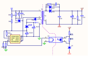
The two protective impedances are connected between the primary winding and the secondary winding of the T2 transformer; the dotted line in the figure below indicates the separation of the 220-240V working voltage part and the low working voltage part(SELV).
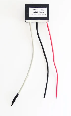
Case 2: Protective impedance used on negative ion generator. As shown in the left figure below, the white line is the high voltage output end, and the other two lines are the power input lines.
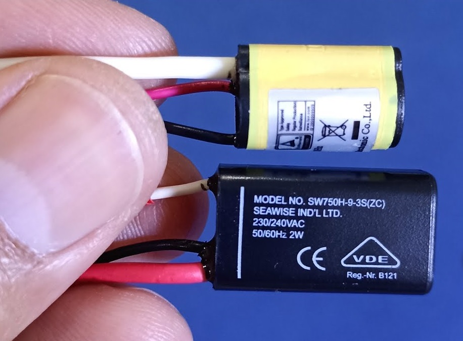
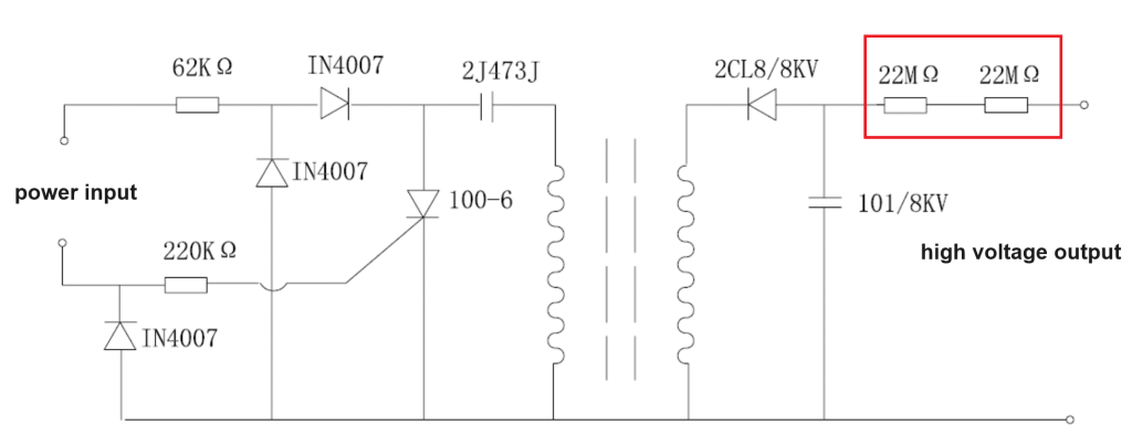
The figure below is the circuit diagram of the negative ion generator. The two resistors selected by the red rectangle are typical protective impedances.
In the picture shown below, are CY1 and CY2 protective impedances?
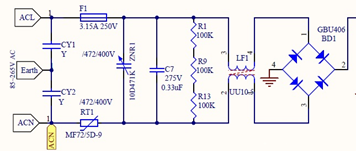
From the definition of the standard, the protective impedance is used in the class II construction, where there is earthing. If the earthing here is defined as protection earthing, then obviously, CY1 and CY2 cannot be defined as protection impedance, because protection impedance is used in class II construction, and here is class I construction. If the earthing here is defined as functional earthing, then there are two problems. First, this is a class I structure, then CY1 and CY2 cannot be defined as protection impedance. Second, if it is a class II structure, CY1 and CY2 can be defined as protection impedance, and then the relevant requirements of protection impedance need to be met. My personal opinion is that CY1 and CY2 are not protective impedances, and we can directly regard them as basic insulation. At the end, in other words, the design shown in the circuit diagram is not accepted by the standard?
If they are protective impedances, then which is need to comply with clause 22.42 – “Protective impedance shall consist of at least two separate components.”.