Clause 3 – How to understand the definition of “functional insulation”
functional insulation: insulation between conductive parts of different potential which is necessary only for the proper functioning of the appliance.
Functional insulation is set because of the functional needs of the appliance. In electrical products, there must be conductive parts with different potentials (different voltages). If the voltage of all energized conductors in the product is the same, the appliance cannot work. Then, there is functional insulation between different conductive parts. Assuming that the rated voltage of the appliance is 220V, there is functional insulation between the two conductors of the power line (live wire and neutral wire), after the rated voltage of 220V is stepped down by the transformer inside the appliance, there is also a voltage difference between the two output pins of the secondary winding of the transformer, so there is also functional insulation, there are also some products that may have a boost circuit inside the product, such as the working voltage at both ends of the starting capacitor connected in series to the AC asynchronous motor is higher than the rated voltage. In this case, there is also functional insulation between the two ends of the capacitor. Then we can actually know that there is functional insulation between conductors that are not on the same conductive circuit. Even on the same conductive circuit, there will be a voltage difference, and functional insulation will still be formed.
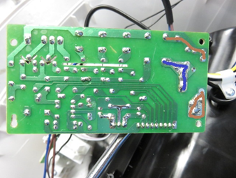
The figure below is a typical functional insulation picture, as shown in the figure on the copper rail layer of the PCB, the brown part of the labeling is the power live wire (two brown positions connected between the current fuse), the blue part of the connection is the neutral wire of the power line, live wire and the neutral wire has a voltage difference between the two lines, so the blue part of the selected copper rail to the brown part of the selected copper rail of the shortest distance between the rails, that is, the functional insulation. In fact, in normal operation, the circuit board in the picture below, the voltage on the copper rail, in many locations are not the same, so the formation of functional insulation, the reader can give their own circuit analysis by the operating voltage of each part.
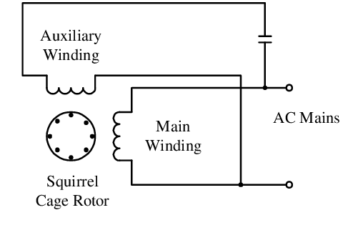
As shown in the figure below, a typical winding connection diagram of an AC asynchronous motor. When the capacitor in the figure is working, the voltage across the capacitor is usually higher than the rated voltage of the product. For example, if the rated voltage is 220V, the voltage across the capacitor measured by the multimeter during operation is usually above 300V. At this time, if the functional insulation between the two ends of the capacitor is evaluated, it is necessary to evaluate it based on a working voltage of more than 300V, however, in actual cases, the functional insulation of the capacitor itself is generally not measured because the terminals of the capacitor are encapsulated inside the capacitor casing; the location that can be measured is the terminal block of the two leads of the capacitor.
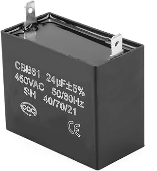
As shown in the figure below, the top view of the CBB61 capacitor. A creepage distance of functional insulation is formed between the wiring tab terminals at both ends of the capacitor along the epoxy resin surface of the package.
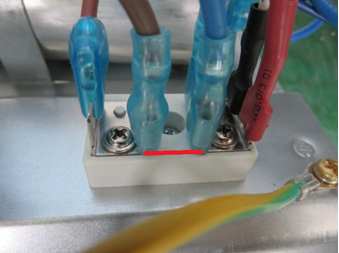
As shown in the figure below, the terminal block has the live wire connected on the left and the neutral wire connected on the right. The position of the red line is the creepage distance of the functional insulation (the clearance can also be determined here).
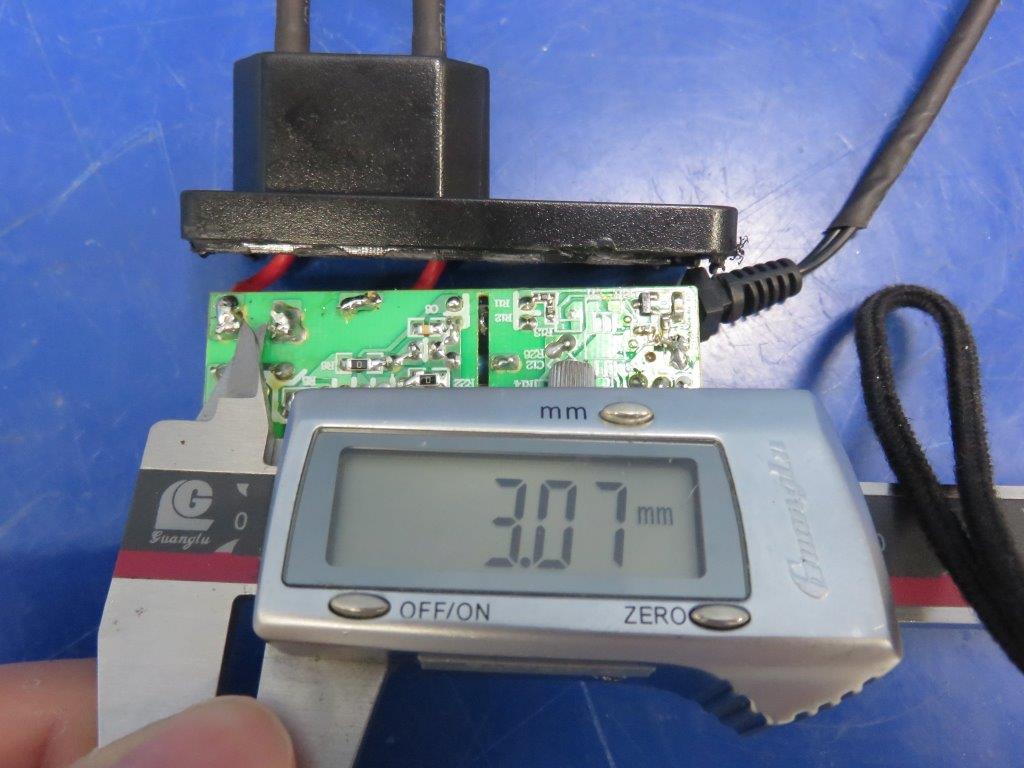
The caliper measurement depicted in the figure below represents the functional insulation between the live and neutral copper tracks of the adapter’s input on the PCB.
