How are the creepage distances and electrical clearances of PTC heating element surfaces determined?
We are discussing here the second structure of the PTC heating element, PTC heating element structure please refer to the explanation of its definition.


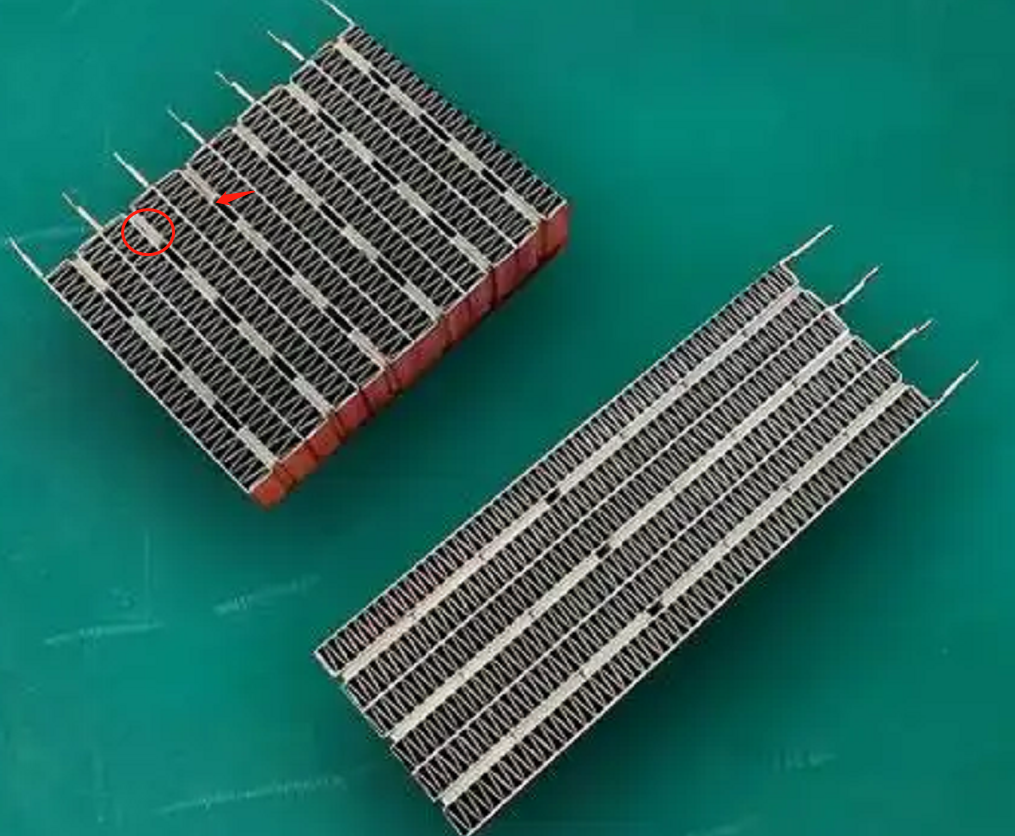
How is the creepage distance of the functional insulation at the location of the red circle in Figure 1 determined?
We all know that NOTE 1 of TABLE 18 section has the following requirements.
NOTE 1 For PTC heating elements, the creepage distances over the surface of the PTC material need not be greater than the associated clearance for working voltages less than 250 V and for pollution degrees 1 and 2. However, the creepage distances between terminations are those specified in the table.
In the first case, the heating units are fixed by means of a conductive adhesive and a heat sink, with some gaps between the heating units, but all the gaps are filled with an insulating adhesive.
As shown in Fig. 2, the heatsinks connected to the fire wire and the heatsinks connected to the zero wire are functionally insulated by means of an insulating structure filled with adhesive, whereby the electrical gaps and creepage distances are formed by the upper surface of the insulating adhesive. Since the environment in which the PTC heating elements are located is of pollution class III, then NOTE 1 of the TABLE 18 section does not apply. Therefore, the requirement for creepage distance is 3.2 mm if it is determined according to the 250 V operating voltage, but of course, we need to use the interpolation method to calculate the creepage distance limit at the rated voltage. Usually, the gap between the two heat sinks is about 2.4mm, then its resulting creepage distance and electrical clearance is generally 2.4mm, the smarter approach is to raise the gap on the insulating adhesive, made into a curved projection, which lengthens the creepage distance and electrical clearance.
The second case, the heating unit through the conductive glue and heat sinks are fixed, leaving a certain gap between the heating unit, but the surface of the heating unit are attached to the insulating adhesive.
And the requirements of the first case is the same, just the middle of the gap if you increase the creepage distance of the problem. In fact, it is not difficult to think of, can be in the middle of the gap near the location of the heating unit to increase the glue, glue can not be laid flat on the side of the heating unit, need to be laid into a U-shaped. Of course, this process is more difficult to realize, not recommended.
In the third case, the heating unit is only fixed by the conductive glue and the heat sink for sticking, and there is a gap between multiple heating units. See Figure 1, the upper left corner of the component. There is no insulating glue attached between the heat generating units or on the surface.
The electrical gap is present in the gaps. What is in dispute here is how to determine the creepage distance. According to conventional logic, there is no creepage distance. According to the definition of creepage distance, creepage distance is in the surface of the insulating material trip, two heat sinks between the heating unit is not an insulating material, so its surface can not form a creepage distance path. Since no creepage distance can be formed, the prerequisite of clause 29.2.4 is not satisfied, and therefore there is no need to assess the creepage distance of functional insulation.
However, I personally still believe that we need to consider creepage distances, because the existence of creepage distances also takes into account the deposition of contaminants on the surface of a material, which can lead to short circuits. Here the PTC heating element generally work in Pollution degree 3, the surface must be for the accumulation of a lot of pollutants, pollutants, if too much, will lead to functional insulation short-circuit, resulting in appliances or power supply lines in the protective device action. This is in fact a less safe means, and the standard does not allow for the operation of protective devices in the supply line.