Clause 3 – How to understand the definition of “double insulation”
double insulation: insulation system comprising both basic insulation and supplementary insulation
The definition is only to simplify the description of basic insulation and supplementary insulation in the standard, using one name to descirbe two names.
As shown in the figure below, the supply cord has two layers of insulation, the inner wire sheath and the outer black wire sheath, which is defined as double insulation.
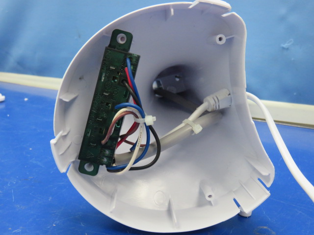
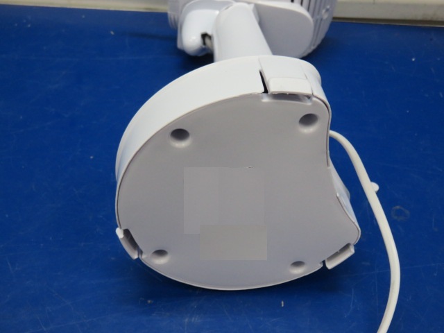
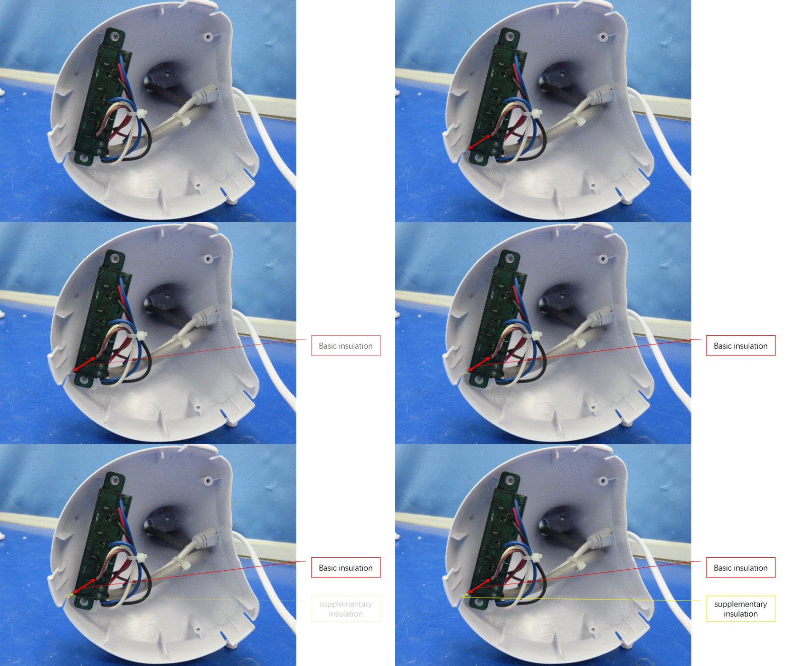
As shown in the following two pictures(fan), the internal lead wires sheath in the left picture is basic insulation, and the bottom plate of the outer casing is additional insulation.


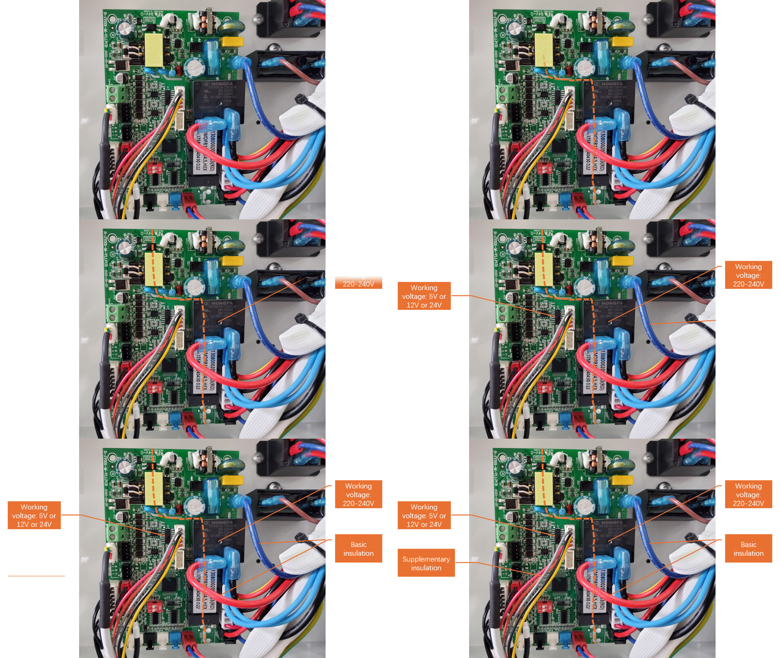
The following circuit board picture has an animation effect. The right side of the dotted line is the inaccessible part with a working voltage of 220-240V, and the left side of the dotted line is the accessible part with a maximum working voltage of 24V (assuming that the structure at the location of the dotted line has met the requirements of double insulation or reinforced insulation). In order to ensure effective isolation, generally speaking, the wires on the right side of the dotted line (red and blue internal wires) cannot touch the relatively thin internal wires on the left. The wire sheath of the right wire is basic insulation, because the wire sheath is in direct contact with the live parts and is the first layer of protection for the live parts. The wire sheath of the left wire can only be defined as supplementary insulation, but whether it meets the requirements for supplementary insulation in clause 29.3 will be analyzed when introducing clause 29.3.
It should be noted here that the wire sheath of the left wire cannot be defined as basic insulation, and the wire sheath of the right wire cannot be supplementary insulation.
