|

A question about functional insulation requirements at the ends of a current fuse

The following circuit diagram
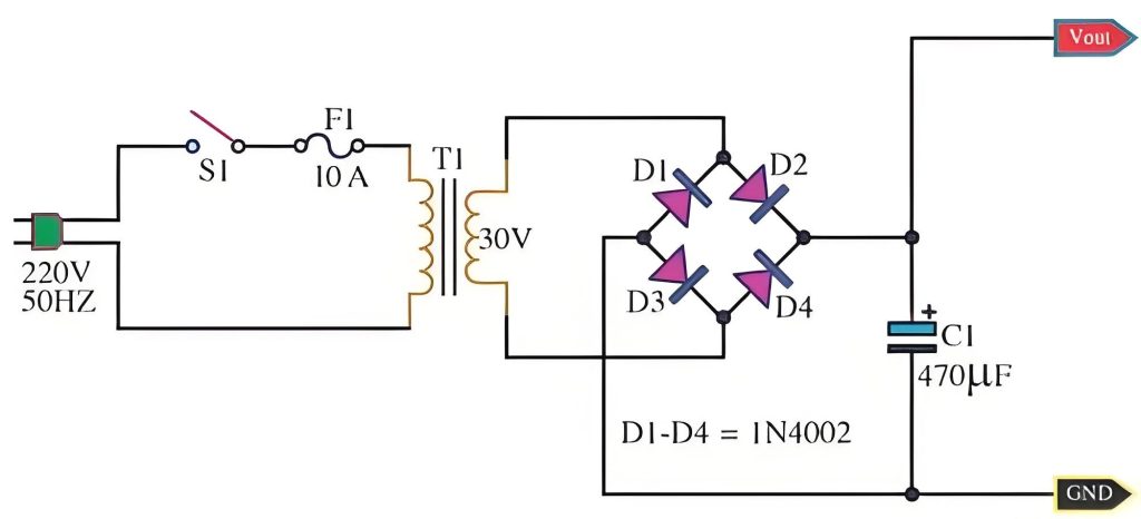
The current fuse in position F1 is usually connected in series with the line.
The photos of the real thing are shown in the following two pictures, the left one is not labeled, the right one shows the location of the current fuse and some other basic information.
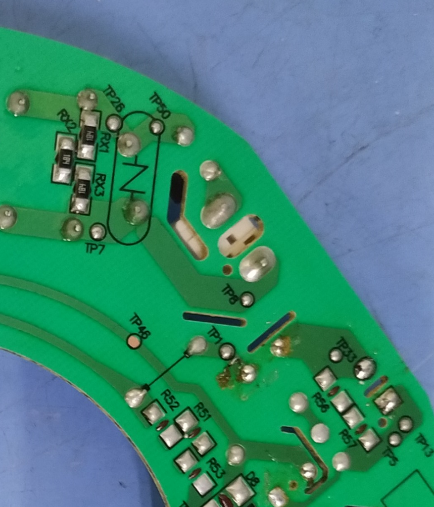
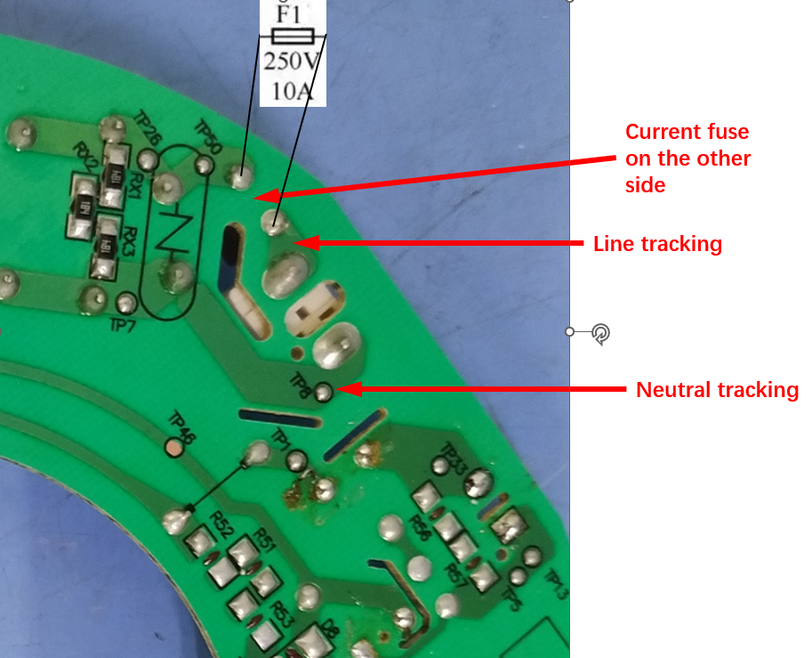
In the diagram above, there is definitely functional insulation between line tracking and neutral tracking, as we have explained in the definition of functional insulation.
So is there functional insulation at the ends of the current fuse? Here you need to measure the distance between two locations, firstly on the front side of the board, on the body of the current fuse, and secondly between the tracking on the board, e.g. as indicated by the black text in the picture above.
Normally, the two ends of a current fuse are insulated, although internally they are connected together. When the internal fuse is broken, the insulated ends are necessary to break the circuit too. In order to ensure that the circuit breaks after the current fuse has broken, it is assumed that there is functional insulation, while the clearance of functional insulation is relatively easy to meet, the creepage distance sometimes does not meet the requirements of the standard, especially in the case of Pollution degree 3.

I think there is no functional insulation here. According to the definition of functional insulation, there needs to be a different potential, and there is no different potential between the two ends of the current fuse under normal operation, so there is no functional insulation under normal operation. When the current fuse is broken, it will appear at both ends of the potential difference, theoretically, there is functional insulation. However, when the current fuse broken and the electrical product does not work properly, it is at least in a non-normal operating condition, and the cause of the current fuse broken is the abnormal operation test from clause 19. According to clause 19.13 of the standard, after the abnormal test need to carry out electrical strength test, the test voltage of functional insulation is twice the working voltage, and there is no requirement for creepage distance and electrical clearance. It might be thought that the accumulation of contamination at the ends of the blown fuse would lead to a short-circuit in the functional insulation, but since the current fuse is broken, there is also the accumulation of contamination, which accumulates very slowly when the appliance is not in operation and no forced convection air can be supplied.
Therefore, when the appliance is in normal operation, there is no functional insulation; when the current fuse broken, it is sufficient to take into account the electrical strength test of clause 19.13, and it is not necessary to measure and evaluate the clearance and creepage distance of the functional insulation.
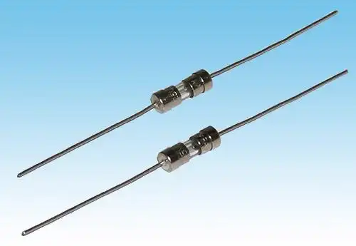
For reference, the following figure shows a physical drawing of the appearance of a current fuse.
Similar Posts

  • 第 3 項 – 「動作電圧」の定義の理解方法

    就労電圧: 機器が定格電圧で供給され、通常の動作で動作し、値が最大になるように制御装置やスイッチング デバイスが配置されている場合に、対象の部品が受ける最大電圧 注 1 動作電圧は共振電圧を考慮しています。 注 2 動作電圧を推定する際、過渡電圧の影響は無視されます。 ザ 定格電圧 は通常、テスト対象のサンプルの電源電圧ですが、通常の動作状態にある機器の内部回路では、電圧がこの電圧より高いか低い回路が存在します 定格電圧。 AC非同期モーターで一般的に使用される一般的なファンは、コンデンサを始動する必要があり、両側の始動コンデンサ電圧は一般に 定格電圧定格電圧 電圧の;明らかに、家電製品には複数の動作電圧が存在する可能性があります。規格によれば、回路のこの部分(定義では「検討中の部品」)が動作電圧に基づいて規格の安全要件を満たしているかどうかを評価し、判断する必要がある場合があります。この場合、規格で定義されている動作回路で発生する可能性のある最大電圧を考慮する必要があります。定義によれば、動作電圧の最大値を得るには、製品に以下のものが供給される必要があります 定格電圧 および通常の動作条件で動作します (製品に定格電圧範囲のラベルが付いている場合、通常は 220 ~ 240V の定格電圧など、電圧を供給するための定格電圧範囲の上限として使用されます)。 240V 電源)を使用し、同時に製品内部のコントローラとスイッチングデバイスが定格電圧の電力を供給し、通常の使用条件で動作するように設定する必要があります。電源を供給し、通常の動作条件で動作します。目的は、最高の動作電圧が確実に得られるようにすることであり、評価は製品が最も過酷な動作条件にあることに基づいて行われます。なお、ここではピークテストについて特に言及していないため、動作電圧は実効値となります。 第 29 条の沿面距離の決定は、動作電圧に基づいて沿面距離の制限を決定するため、製品の特定の場所での動作電圧が必要になります。第 13 条の電気強度試験では、絶縁構造に適用される試験電圧も動作電圧に基づいています。 The determination of creepage distances in clause 29 is based on the working voltage to determine the creepage distance limit, which then requires the working…

  • A question about whether the second part of clause 21.2 needs to be tested.

    We know that clause 29.3.2 and clause 21.2 are two separate clauses and they are not very much related, which means that the product being assessed needs to fulfill both clauses if applicable.A reinforced insulation system consisting of three separate layers of insulating material or what could be considered a double insulation system, Each layer…

  • 第3項「機能絶縁」の定義の見方

    機能的絶縁: 電位の異なる導電性部分間の絶縁であり、機器が適切に機能するためにのみ必要です。 下の図は典型的な機能絶縁の図です。PCB の銅レール層の図に示されているように、ラベルの茶色の部分は電源活線 (電流ヒューズ間に接続されている 2 つの茶色の位置)、青色の部分です。接続は電力線の中性線であり、活線であり、中性線には 2 つの線の間に電圧差があるため、選択した銅線レールの青色の部分と選択した銅線レールの茶色の部分の間の最短距離になります。レール、つまり機能絶縁体です。実際、通常の動作では、下の写真の回路基板、銅レール上の電圧は多くの場所で同じではないため、機能絶縁の形成により、読者は動作電圧によって独自の回路分析を行うことができます。各部分。 AC 非同期モーターの一般的な巻線接続図は次の図のようになります。図のコンデンサが動作しているとき、コンデンサの両端の電圧は通常、製品の定格電圧よりも高くなります。たとえば、定格電圧が 220V の場合、動作中にマルチメータで測定されるコンデンサの両端の電圧は通常 300V を超えます。このとき、コンデンサの両端間の機能絶縁を評価する場合、300V以上の使用電圧を基準に評価する必要がありますが、実際にはコンデンサ自体の機能絶縁は一般的には可能ではありません。コンデンサの端子がコンデンサのケース内に封入されているため測定されます。測定できる箇所はコンデンサの2本のリード線の端子台です。 下図に示すように、端子台には左側に活線が接続され、右側に中性線が接続されています。赤い線の位置は機能絶縁体の沿面距離です(クリアランスもここで決定できます)。 下の図に示されているキャリパーの測定値は、PCB 上のアダプターの入力のライブ銅線と中性銅線の間の機能絶縁を表しています。 As shown in the figure below, the terminal block has the live wire connected on the left and the neutral wire connected on the right. The position of the red line is the creepage distance of the…

  • How are the creepage distances and electrical clearances of PTC heating element surfaces determined?

    We are discussing here the second structure of the PTC heating element, PTC heating element structure please refer to the explanation of its definition. How is the creepage distance of the functional insulation at the location of the red circle in Figure 1 determined? We all know that NOTE 1 of TABLE 18 section has…

  • IEC 60335-1の表17および表18

    表 17 と表 18 には、「動作電圧と gt; 10 V および ≤ 630 V については、電圧が表に指定されていない場合、沿面距離の値は補間によって求められる場合があります。」という注記があります。 動作電圧が表に記載されている値ではない場合、通常は制限値を取得するために計算する必要があります。便宜上、Excel テーブルを用意しました。テスターはテーブルを直接クエリして、対応する制限値を取得できます。 ダウンロード

  • 第 3 項 – 「沿面距離」の定義の理解方法

    沿面距離: 2 つの導電性部品間、または導電性部品とアクセス可能な表面間の絶縁体表面に沿った最短距離。 電荷は空気中を指向性を持って伝播し、電流を形成します。これがクリアランスの意味です。完全に絶縁された材料はないため、実際には電荷は絶縁材料自体を通って伝播する可能性もあります。通常のA4印刷用紙の両面と厚さ2mmのトレッドゴム材の両面に電位の異なる2つの電極を印加した場合、2つの電極間に形成される電流の差は非常に大きくなります。電荷は、絶縁材料の表面に沿って方向性を持って伝播することもあります。異なる材料の表面における電荷伝播の影響も異なります。絶縁材の表面に他の物質(汚染物質)が付着している場合、電荷伝播の影響も異なります。電荷が絶縁材料の表面に沿って伝播して感電を引き起こすのを防ぐために、沿面距離の定義と要件が作成されます。絶縁材料本体を通した電荷の伝播により、第 29 条の最初の段落に記載されている固体絶縁要件が生成されます。第 29.2 条には、沿面距離の要件が示されています。 沿面距離の定義は IEC 60664-1:2020 規格に基づいています。沿面距離を説明する必要があるため、IEC 60664-1:2020規格の図4から図14までの図を示す必要があります。ここで、読者は「X mm」をどのように決定するかを慎重に検討する必要があります。沿面距離を形成する経路上に溝がある場合、橋溝の状況が発生します。私は個人的に、ブリッジの主な原因は溝への汚染物質の堆積であると考えています。これらの汚染物質は主に粉塵であり、湿った粉塵は導電性が高くなります。したがって、規格の原文をコピーすると、次の 3 つの前提条件があります。– 溝を横切る距離が指定された幅 X (表 1 を参照) より小さい場合、沿面距離は溝を直接横切って測定され、溝の輪郭は考慮されません (図 4 を参照)– 溝を横切る距離が指定された幅 X 以上である場合 (表 1 を参照)、沿面距離は溝の輪郭に沿って測定されます (図 5 を参照)。– 凹部は、指定された幅 X に等しい長さを持ち、最も不利な位置に配置された絶縁リンクで橋渡しされていると想定されます (図 6 を参照)。– 相互に異なる位置を想定できる部品間で測定される隙間と沿面距離は、これらの部品が最も不利な位置にあるときに測定されます。 条件: 検討中のパスには、幅 X mm 未満の任意の深さの平行または収束側面の溝が含まれています。ルール: クリアランスと沿面距離は、図に示すように溝を直接横切って測定されます。 クリアランス沿面距離 条件: 検討中のパスに、任意の深さで X mm 以上の平行な側面の溝が含まれているルール:クリアランスとは「見通し」の距離です。沿面経路は溝の輪郭に従います。 クリアランス沿面距離 条件:…