|

If the PCB is sealed with solid sealant, how to determine the creepage distance and clearance?

functional insulation as well as other insulation exists on circuit boards. Typically, the surface environment of a circuit board is determined to be either Pollution degree 3 or pollution degree 2.
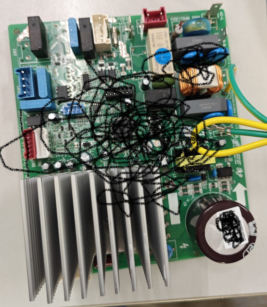
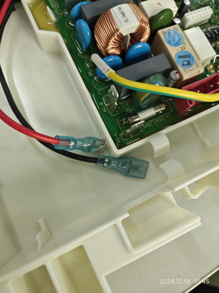
If the circuit board is mounted in an electrical box and sealed with a solid sealant, the sealing will look as follows:

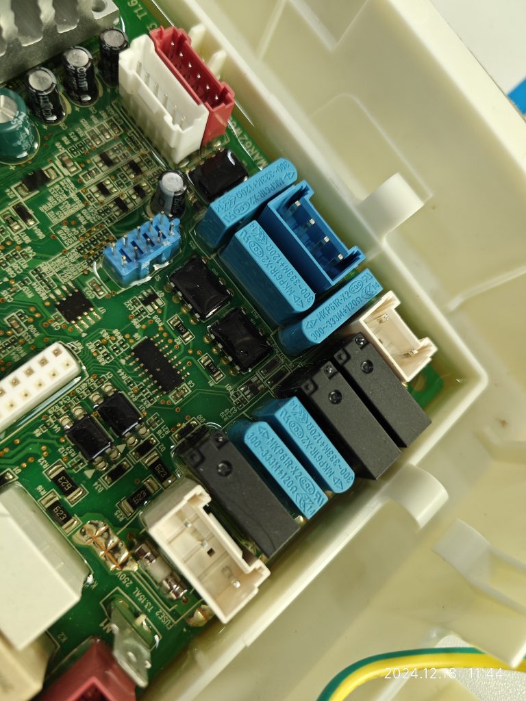
What should be the pollution degree of the functional insulation between the copper tracks on the PCB and between the energized parts on the component?
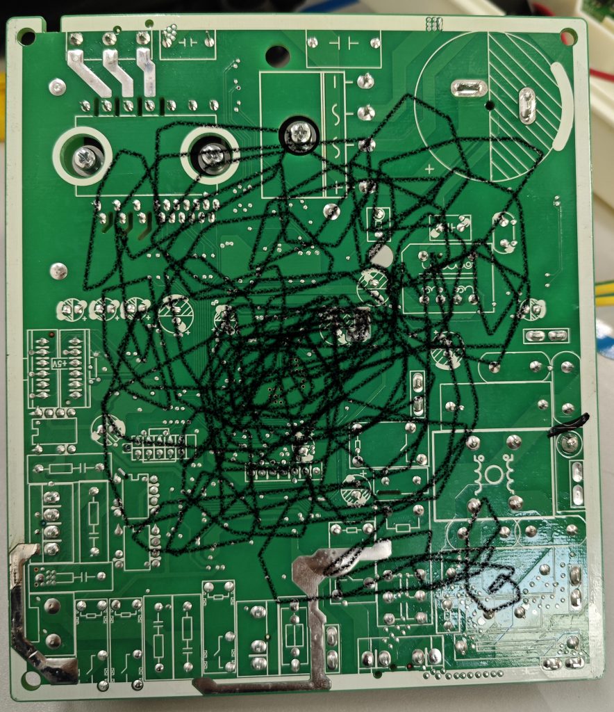
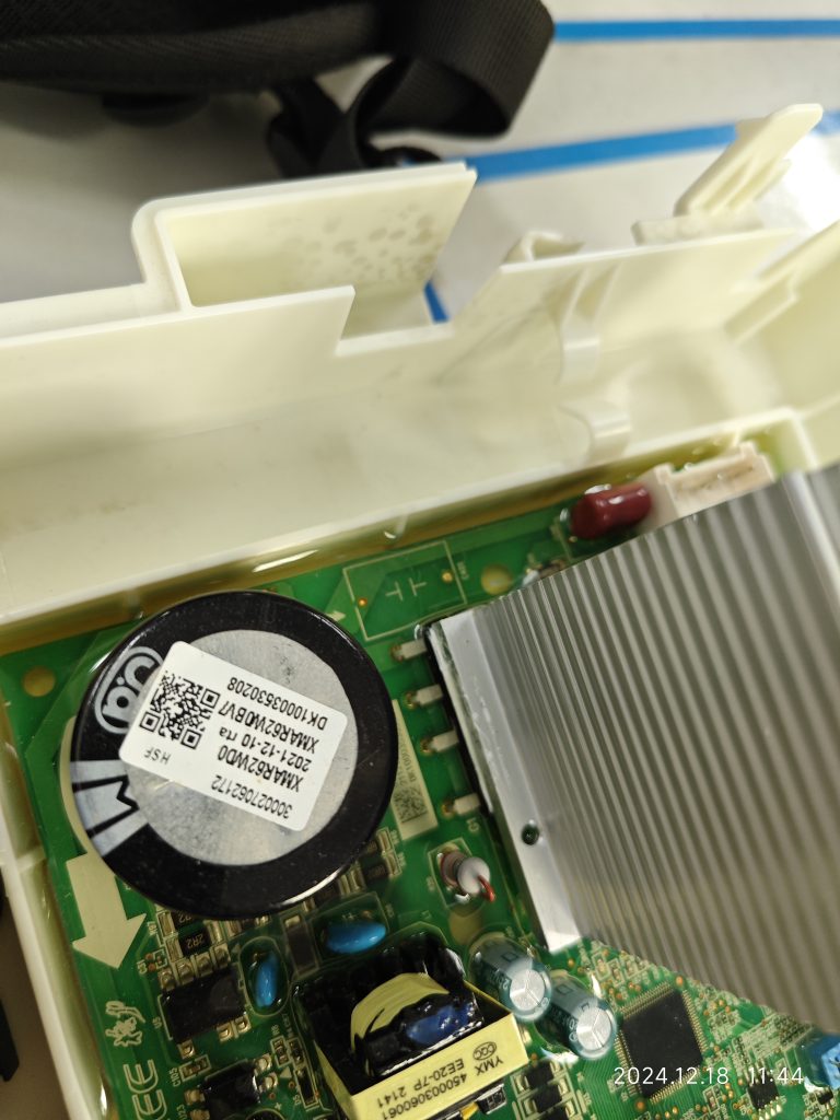
Here, the functional insulation is located inside the solid sealant and there is no contact between the path of the functional insulation and the outside air. According to the definition of electrical clearance, it can be assumed that there is no electrical clearance here. At the same time, the creepage distance is defined along the surface of the insulation, and obviously, there is no surface here either.
It may be argued that there is still a gap between the solid sealant and the PCB material, and that an clearance and creepage distance can be formed, but it is a pollution degree 1. This view is more conservative, because even if a gap is formed, it is not a continuous gap.
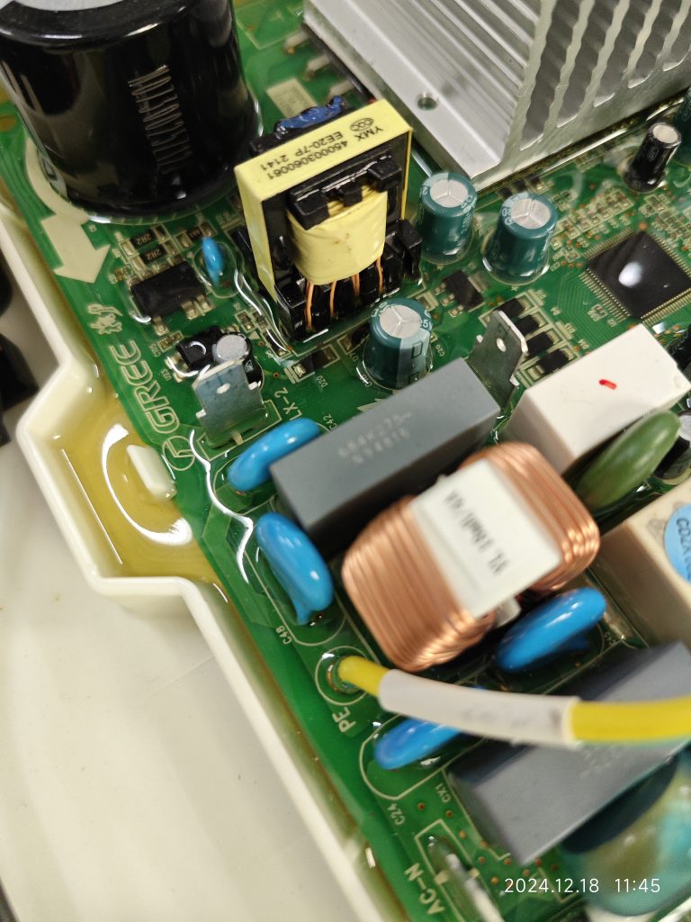
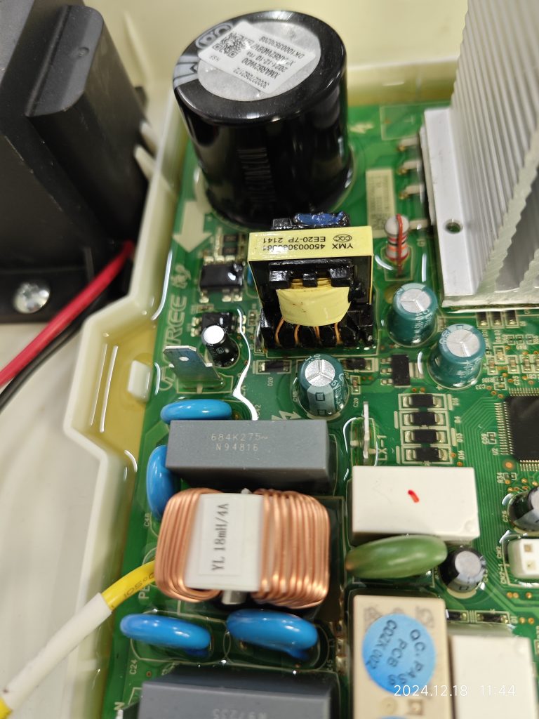
At the same time, the pictures show that this solid state sealant fills so well that it is essentially impossible to create a gap. The manufacturer also indicates that there is a vacuuming procedure prior to filling the solid state sealant. When we evaluate this type of structure, we can have some control over the material and specification of the solid state sealant, as well as some control over the filling process.
There may also be reinforced insulation internally, as there are isolation measures between the 220-240V circuit portion and the SELV circuit, which are judged by the same rules for clearance and creepage distances as functional insulation.

Similar Posts

  • How are the creepage distances and electrical clearances of PTC heating element surfaces determined?

    We are discussing here the second structure of the PTC heating element, PTC heating element structure please refer to the explanation of its definition. How is the creepage distance of the functional insulation at the location of the red circle in Figure 1 determined? We all know that NOTE 1 of TABLE 18 section has…

  • 第 3 項 – 「安全絶縁変圧器」の定義の理解方法

    安全絶縁変圧器:安全超低電圧で機器または回路に供給することを目的とした、少なくとも二重絶縁または強化絶縁と同等の絶縁によって入力巻線が出力巻線から電気的に分離された変圧器 ここで言う変圧器は、機器や回路に電力を供給するために使用されます。最も一般的な変圧器は回路に電力を供給し、いくつかの変圧器は電化製品に電力を供給します。ここで重要となるのは入力巻線と出力巻線の絶縁対策であり、二重絶縁もしくは強化絶縁タイプ、または同等の絶縁が必要となります。この要件は、一次巻線と二次巻線が十分な絶縁を有することを保証することです。絶縁が十分であれば、変圧器の一次巻線と二次巻線間の絶縁は比較的安全です。二重の保護予防策。 スイッチの電源基板に使用される最初の種類のトランス。このタイプの変圧器は、同じ磁気コア上に一次巻線と二次巻線を重ね合わせます。したがって、一次側と二次側の間の沿面距離と電気的空間を確保するために、巻線を上下の端面に配置することはできません。以下の図に示すように、巻線は上下の端面から一定の距離にある必要があります。 安全絶縁トランスの全体図 安全絶縁トランスの全体図 The other is a drawer-type linear transformer, as shown below:

  • Clause 3 – How to understand the definition of “thermostat”

    thermostat: temperature-sensing device, the operating temperature of which may be either fixed or adjustable and which during normal operation keeps the temperature of the controlled part between certain limits by automatically opening and closing a circuit. The thermostat itself does not control the temperature, the thermostat senses the temperature and controls the temperature by switching…

  • 第 3 項 – 「クラス II アプライアンス」の定義の理解方法

    クラスⅡ機器:感電に対する保護を必要としない機器 基礎絶縁 ただし、追加の安全予防措置が提供される場合のみ 二重絶縁 または 強化絶縁、保護接地の規定や設置条件への依存はありません。 注 1 このようなアプライアンスは、次のタイプのいずれかになります。– 銘板、ネジ、リベットなどの絶縁された部品を除き、すべての金属部品を覆う、耐久性があり実質的に連続した断熱材の筐体を備えた機器 充電部 同等以上の絶縁により 強化絶縁;このような器具は断熱材入りと呼ばれます クラス II 機器;– 実質的に連続した金属製の筐体を備えた機器 二重絶縁 または 強化絶縁 は全体で使用されます。このような器具は金属ケースと呼ばれます クラス II 機器;– 断熱材で覆われた機器を組み合わせた器具 クラス II 機器 そして金属ケース クラス II 機器.注2 絶縁被覆の筐体 クラス II 機器 の一部または全体を形成する場合があります 補助絶縁 またはの 強化絶縁. ここでは二重の予防策の観点から考えていきます。基礎絶縁に加えて、製品には別の絶縁層も必要です。つまり、いずれかの層の絶縁が機能しなくなった場合でも、別の層の絶縁が保護の役割を果たすことを保証する二重絶縁対策です。強化絶縁による感電防止効果は二重絶縁と同等の場合が多く、二重の予防策としても有効と考えられます。規格によって定義されたクラス II 機器は、機器が独自のケーシング、絶縁電線、および絶縁電線のシースによって二重絶縁の効果を達成することを主に強調しています。接地対策が施された機器はクラス I 機器であるため、クラス II 機器には保護接地がありません。 クラス 0 機器を除き、大面積のプラスチックまたは絶縁ハウジングを備えたすべての機器は、通常、クラス II 機器として設計されています。ただし、金属ハウジングを備えたモーターもあり、その製品はクラス II 機器の要件を満たすことができますが、モーターには保護接地措置が講じられています。このアプライアンスはクラス I…

  • |

    A question about functional insulation requirements at the ends of a current fuse

    The following circuit diagram The current fuse in position F1 is usually connected in series with the line.The photos of the real thing are shown in the following two pictures, the left one is not labeled, the right one shows the location of the current fuse and some other basic information. In the diagram above,…