Clause 3 – How to understand the definition of “detachable power supply part”

detachable power supply part: part of the appliance the output of which is intended to be detachable from the class III construction part of the appliance.
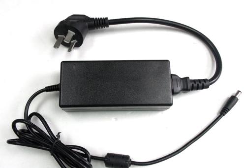
Note 1 to entry: Means of detachment are a flexible cord and connector or an appliance outlet fitted to the detachable power supply part.

This actually defines a detachable adapter. Similar to our laptop chargers, cell phone chargers, they can be unplugged from the appliance. NOTE has actually been explained in more detail.

Similar Posts

  • Clause 3 – How to understand the definition of “detachable part”

    detachable part: part that can be removed or opened without the aid of a tool, a part that is removed or opened in accordance with the instructions for use, even if a tool is needed for removal, or a part that does not fulfil the test of 22.11.NOTE 1 If for installation purposes a part…

  • Clause 3 – How to Understand the Definition of “off position”

    off position: stable position of a switching device in which the circuit controlled by the switch is disconnected from its supply or, for electronic disconnection, the circuit is de-energized.NOTE The off position does not imply an all-pole disconnection. With reference to the content in the NOTE, both all-pole disconnection and single-pole disconnection are a stable…

  • 第3項「機能絶縁」の定義の見方

    機能的絶縁: 電位の異なる導電性部分間の絶縁であり、機器が適切に機能するためにのみ必要です。 下の図は典型的な機能絶縁の図です。PCB の銅レール層の図に示されているように、ラベルの茶色の部分は電源活線 (電流ヒューズ間に接続されている 2 つの茶色の位置)、青色の部分です。接続は電力線の中性線であり、活線であり、中性線には 2 つの線の間に電圧差があるため、選択した銅線レールの青色の部分と選択した銅線レールの茶色の部分の間の最短距離になります。レール、つまり機能絶縁体です。実際、通常の動作では、下の写真の回路基板、銅レール上の電圧は多くの場所で同じではないため、機能絶縁の形成により、読者は動作電圧によって独自の回路分析を行うことができます。各部分。 AC 非同期モーターの一般的な巻線接続図は次の図のようになります。図のコンデンサが動作しているとき、コンデンサの両端の電圧は通常、製品の定格電圧よりも高くなります。たとえば、定格電圧が 220V の場合、動作中にマルチメータで測定されるコンデンサの両端の電圧は通常 300V を超えます。このとき、コンデンサの両端間の機能絶縁を評価する場合、300V以上の使用電圧を基準に評価する必要がありますが、実際にはコンデンサ自体の機能絶縁は一般的には可能ではありません。コンデンサの端子がコンデンサのケース内に封入されているため測定されます。測定できる箇所はコンデンサの2本のリード線の端子台です。 下図に示すように、端子台には左側に活線が接続され、右側に中性線が接続されています。赤い線の位置は機能絶縁体の沿面距離です(クリアランスもここで決定できます)。 下の図に示されているキャリパーの測定値は、PCB 上のアダプターの入力のライブ銅線と中性銅線の間の機能絶縁を表しています。 As shown in the figure below, the terminal block has the live wire connected on the left and the neutral wire connected on the right. The position of the red line is the creepage distance of the…

  • Clause 3 – How to Understand the Definition of “visibly glowing heating element”

    visibly glowing heating element: heating element that is partly or completely visible from the outside of the appliance and has a temperature of at least 650 °C when the appliance has been operated under normal operation at rated power input until steady conditions have been established. The heating element needs to be able to emit…

  • 第 3 項 – 「タイプ Y アタッチメント」の定義の理解方法

    タイプ Y アタッチメント: 製造元、そのサービス代理店、または同様の資格を持つ担当者が交換を行うための電源コードの取り付け方法。 次の 2 つの写真に示すように、アプライアンスの底部にあるカバーを取り外すと、コード クランプと内部電源コード コネクタが見えます。底部カバーの取り外しは比較的簡単ですが、電源コードが同様のニップルコネクタに接続されているか、機械的に固定されている場合は、電源コードを再接続するために専門の工具や破壊が必要となり、電源コードの交換が困難になります。この構造をタイプ Y アタッチメントとして定義する方が合理的です。 As shown in the following two pictures, after removing the cover at the bottom of the appliance, you can see the cord clamp and the internal supply cord connector. Removing the bottom cover is relatively easy, but if the power cord is connected with…