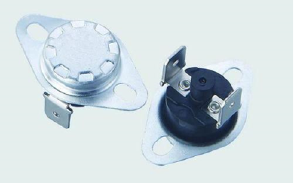
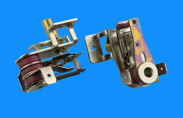
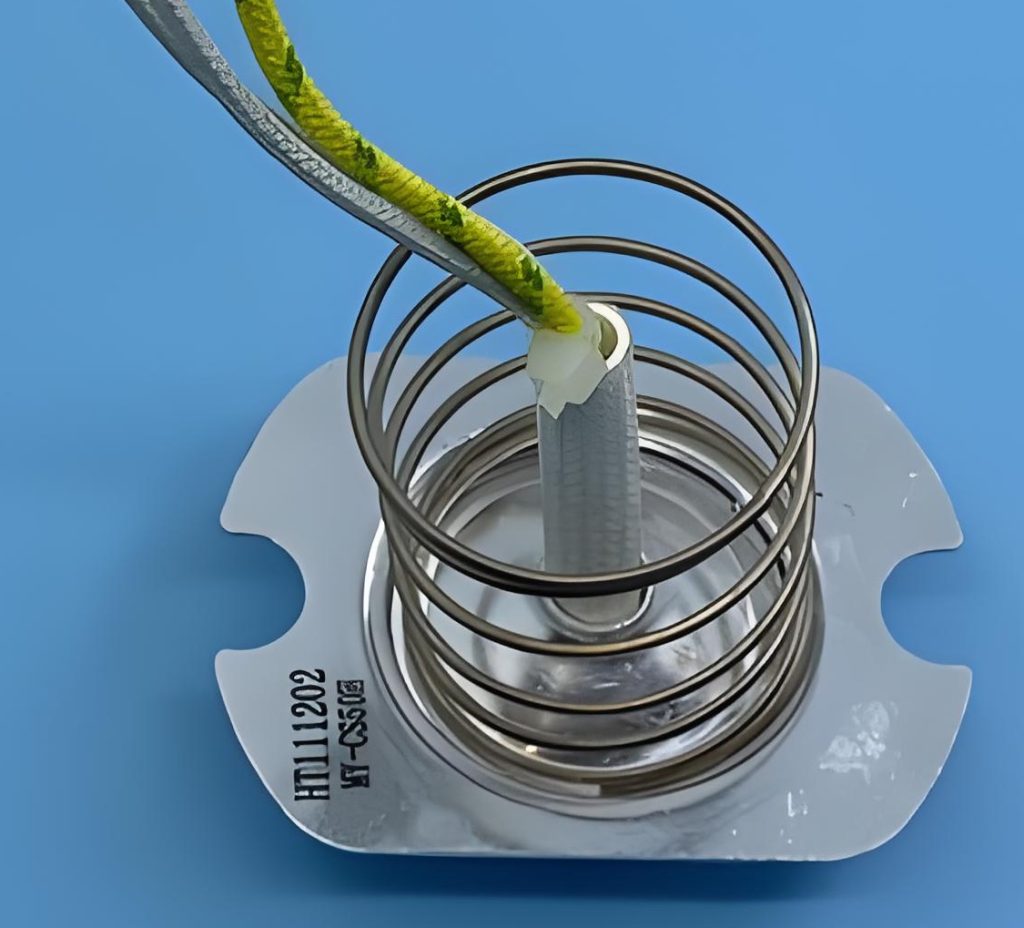
Clause 3 – How to understand the definition of “thermostat”

thermostat: temperature-sensing device, the operating temperature of which may be either fixed or adjustable and which during normal operation keeps the temperature of the controlled part between certain limits by automatically opening and closing a circuit.

The thermostat itself does not control the temperature, the thermostat senses the temperature and controls the temperature by switching on or off components that affect the temperature, such as the PTC heating element. If the temperature is too high, the thermostat will disconnect the power supply circuit of the heating element, so that the heating element does not heat up, so that the temperature will be lowered; the opposite principle and operation makes the temperature rise. The purpose is to control the temperature within a certain interval range, so that the temperature does not exceed this range, nor below this range. Thermostats are often used in environments where temperature control is required, such as ovens, deep fryers, room heaters, air conditioners, refrigerators, and so on.
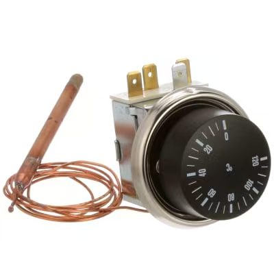
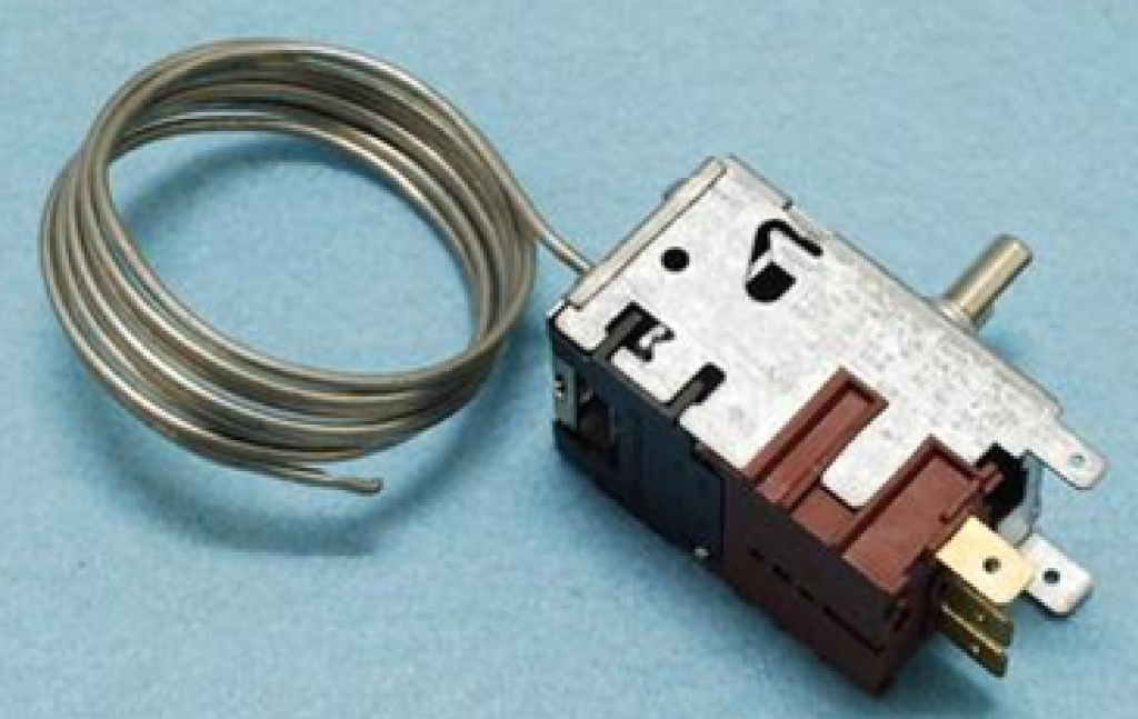
Please note that a thermostat is a controller that functions when the appliance is in normal operation. Many temperature control devices or temperature sensing devices have the same control principle and control method, but not all temperature control devices are thermostats. The controller corresponding to a thermostat is a thermal cut-out, and the one that operates during abnormal operation is a thermal cut-out. This distinction in the standard indicates that the requirements for evaluating a thermal cut-out are different from those for a thermostat, and we will describe the differences in a later clause.

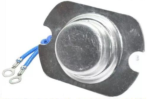
Magnetic steel thermostat for electric pressure cooker
Similar Posts

  • Clause 3 – How to understand the definition of “electronic component”

    electronic circuit: circuit incorporating at least one electronic component. The standard references electronic circuits in clause 19.11, clause 19.11.1, and clause 22.5. These requirements are additional to those for electronic circuits. The standard recognizes that electronic circuits alone cannot provide adequate protection. Electronic circuits may be susceptible to interference and malfunction, or they may be…

  • How are the creepage distances and electrical clearances of PTC heating element surfaces determined?

    We are discussing here the second structure of the PTC heating element, PTC heating element structure please refer to the explanation of its definition. How is the creepage distance of the functional insulation at the location of the red circle in Figure 1 determined? We all know that NOTE 1 of TABLE 18 section has…

  • 第3項 「第3種建築物」の定義の見方

    クラスⅢ構造:感電に対する保護が安全特別低電圧に依存しており、安全特別低電圧以上の電圧が発生しない機器の一部注記 SELV での供給に加えて、基礎絶縁が必要な場合があります。 8.1.4を参照してください。注 2 機器の主要部分が SELV で動作し、取り外し可能な電源ユニットと一緒に納入される場合、機器のこの主要部分はクラス I 機器またはクラス II 機器のクラス III 構造とみなされます。 アプライアンスはプラグイン可能なアダプター (保護接地なし) によって電力を供給され、アダプターとアプライアンスは一緒にユーザーに配送されます。アダプターとアプライアンスは合わせてクラス II アプライアンスとして判断されます。アダプターはクラス II であるため、これによって感電に対する保護のクラスが決まります。ただし、機器 – ファンのみはクラス III 構造、つまりクラス II 機器内のクラス III 構造です。 もちろん、スイッチ電源 PCB が機器に組み込まれており、このスイッチ電源 PCB が SELV 回路を提供できるという別の状況もあります。そして、SELV回路部分はクラスII構造となっております。 Of course, there is another situation, that is, a switch power supply PCB is embedded in the appliance, and…

  • 第3項 – 「安全特別低電圧」の定義の見方

    安全特別低電圧: 導体間および導体とアース間の電圧は 42 V を超えず、無負荷電圧は 50 V を超えない 安全特別低電圧が主電源から得られる場合、安全絶縁を介する必要があります。 注 1 指定された電圧制限は、安全絶縁変圧器が定格電圧で供給されるという前提に基づいています。注 2 安全特別低電圧は SELV とも呼ばれます。 はじめに-1 。また、本項で定義する「安全」は、SELV を使用者が直接触れることができる絶対的な安全を意味するものではありません。ユーザーは、セクション 8.1.4 の要件を満たす SELV 回路のみに触れることができます。この電圧は通常、安全絶縁変圧器または別の巻線を備えたコンバータを通じて電圧を降圧することによって得られます。通常、これは安全絶縁変圧器を通じて得られます。ここで、別個の巻線を備えた安全絶縁変圧器またはコンバータは、一次巻線と二次巻線が物理的に構造的に分離されていることを保証できます。つまり、一次巻線と二次巻線が直接接触しないようにすることができます。この別巻線による回路分離に対応した電圧調整方式の一般的な例は、220V 回路に抵抗とコンデンサを直列に並列接続する RC 降圧方式です。 RC降圧方式では、回路内で高圧部と低圧部が接続されます。明らかに、物理的手段によって回路を分離する前者の方法の方が安全です。単純な物理的分離である場合でも、安全要件を満たすことはできません。規格で要求される絶縁は二重絶縁または強化絶縁の要件を満たす必要があります。簡単に言うと、高電圧部分と低電圧部分の間に非常に単純な絶縁(低温耐性を持つ薄いプラスチックシートなど)がある場合、この絶縁は高温または高電圧条件下で破損しやすく、基本的には絶縁できません。このプラスチックシートの層は絶縁の役割を果たしますが、高電圧回路と低電圧回路を物理的に分離することもあります。二重絶縁と強化絶縁の絶縁要件も二重保護の手段です。下の図に示すように、トランスには一次巻線と二次巻線を分離するためにディスクに垂直に配置された 3 つのプラスチック ブラケットがあり (一次巻線と二次巻線の外側には青いプラスチック テープが巻かれています)、一次巻線と二次巻線は物理的に隔離されています。 下の図に示すように、トランスには中央の一次巻線と二次巻線に黄色いテープが巻かれています。強化絶縁の沿面距離要件を満たしているかどうかを確認するには、2 つの巻線間の黒いブラケットの沿面距離に特に注意を払う必要があります。そうでない場合、その変圧器は安全絶縁変圧器として判断できません。 安全絶縁トランスの構造については次回詳しく説明します。 As shown in the figure below, the transformer has yellow tape wrapped around the primary and secondary windings in the…

  • 第3項「機能絶縁」の定義の見方

    機能的絶縁: 電位の異なる導電性部分間の絶縁であり、機器が適切に機能するためにのみ必要です。 下の図は典型的な機能絶縁の図です。PCB の銅レール層の図に示されているように、ラベルの茶色の部分は電源活線 (電流ヒューズ間に接続されている 2 つの茶色の位置)、青色の部分です。接続は電力線の中性線であり、活線であり、中性線には 2 つの線の間に電圧差があるため、選択した銅線レールの青色の部分と選択した銅線レールの茶色の部分の間の最短距離になります。レール、つまり機能絶縁体です。実際、通常の動作では、下の写真の回路基板、銅レール上の電圧は多くの場所で同じではないため、機能絶縁の形成により、読者は動作電圧によって独自の回路分析を行うことができます。各部分。 AC 非同期モーターの一般的な巻線接続図は次の図のようになります。図のコンデンサが動作しているとき、コンデンサの両端の電圧は通常、製品の定格電圧よりも高くなります。たとえば、定格電圧が 220V の場合、動作中にマルチメータで測定されるコンデンサの両端の電圧は通常 300V を超えます。このとき、コンデンサの両端間の機能絶縁を評価する場合、300V以上の使用電圧を基準に評価する必要がありますが、実際にはコンデンサ自体の機能絶縁は一般的には可能ではありません。コンデンサの端子がコンデンサのケース内に封入されているため測定されます。測定できる箇所はコンデンサの2本のリード線の端子台です。 下図に示すように、端子台には左側に活線が接続され、右側に中性線が接続されています。赤い線の位置は機能絶縁体の沿面距離です(クリアランスもここで決定できます)。 下の図に示されているキャリパーの測定値は、PCB 上のアダプターの入力のライブ銅線と中性銅線の間の機能絶縁を表しています。 As shown in the figure below, the terminal block has the live wire connected on the left and the neutral wire connected on the right. The position of the red line is the creepage distance of the…

  • Clause 3 – How to Understand the Definition of “visibly glowing heating element”

    visibly glowing heating element: heating element that is partly or completely visible from the outside of the appliance and has a temperature of at least 650 °C when the appliance has been operated under normal operation at rated power input until steady conditions have been established. The heating element needs to be able to emit…