Clause 3 – How to understand the definition of “protective electronic circuit”

protective electronic circuit: electronic circuit that prevents a hazardous situation under abnormal operating conditions.
NOTE Parts of the circuit may also be used for functional purposes.

With the advancement of technology, more and more electronic circuits are being used in household electrical products, and these electronic circuits are usually integrated on PCBs. They use microprocessor chips and their burned-in programmes to complete the established functions, which include some regular operating functions and also some protective functions, which are defined as prevents a hazardous situation under abnormal operating conditions.

Generally speaking, it is difficult to distinguish which part of the circuit is protective electronic circuit, usually we will first carry out the abnormal test in clause 19, through the test phenomenon to determine whether there is an electronic circuit involved in the protective function, if there is, we need to find out which part of the circuit is protective electronic circuit according to the circuit schematic diagram and the test phenomenon. If so, we need to find out which part of the circuit is protective electronic circuit according to the schematic diagram and the test phenomenon, which requires analysts to have basic knowledge of circuits. Annex Q (informative) Sequence of tests for the evaluation of electronic circuits gives a flowchart for the evaluation of electronic circuits and protective electronic circuits. clearer.
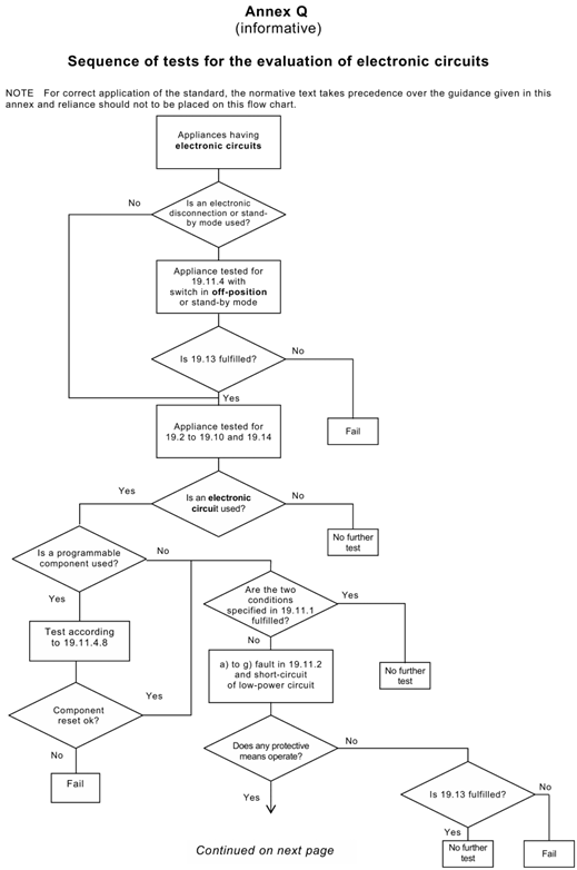
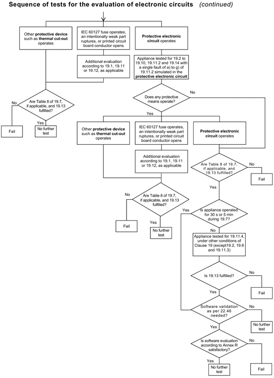
Annex Q

Similar Posts

  • |

    If the PCB is sealed with solid sealant, how to determine the creepage distance and clearance?

    functional insulation as well as other insulation exists on circuit boards. Typically, the surface environment of a circuit board is determined to be either Pollution degree 3 or pollution degree 2.If the circuit board is mounted in an electrical box and sealed with a solid sealant, the sealing will look as follows: What should be…

  • |

    Clause 3 – How to understand the definition of “room temperature”

    room temperature: ambient temperature specified in the general conditions for the tests.Note 1 to entry: The ambient temperature is specified in 5.7. This item comes from standard IEC 60335-1:2020 edition 6.0. In commented version (CMV) of the official standard IEC 60335-1:2020 edition 6.0 allows the user to identify the changes made to the previous edition…

  • 第 3 項 – 「クラス 0I アプライアンス」の定義の理解方法

    クラス 0I 機器:全体に少なくとも基礎絶縁があり、接地端子が組み込まれているが、接地線のない電源コードと接地接点のないプラグを備えた機器 機器には外部保護導体(保護接地導体)を接続するための端子がありますが、固定配線には機器と保護導体を接続するための電線がなく、機器内部に接地導通を伝えるための配線や構造が設けられている場合があります。 日本では、以下のようなクラス0I機器専用のプラグがあります。 私の理解では、現在、クラス 0I 機器を使用しているのは日本だけです。通常、電源コードにはアース線が付いていますが、プラグ内のアースピンによってアースは行われません。代わりに、ツールを使用して別の端子または接地リングを接続し、効果的な接地を実現します。同様に、アプライアンスにもアース端子があります。設置前、この端子は外部配線に接続されておらず、通常は使用中および設置中に接続されます。

  • Clause 3 – How to understand the definition of “temperature limiter”

    temperature limiter: temperature-sensing device, the operating temperature of which may be either fixed or adjustable and which during normal operation operates by opening or closing a circuit when the temperature of the controlled part reaches a pre-determined value.Note 1 to entry: A temperature limiter does not make the reverse operation during the normal duty cycle…

  • 第 3 項 – 「クラス 0 アプライアンス」の定義の理解方法

    クラス 0 機器: 感電に対する保護が基礎絶縁のみに依存しており、導電性のアクセス可能な部品があったとしても、設備の固定配線内の保護導体に接続するための手段がなく、万一の場合に信頼できる機器。環境に設置された基礎断熱材の欠陥。注記 クラス 0 機器には、基礎絶縁の一部または全体を形成する絶縁材料のエンクロージャ、または適切な絶縁によって充電部から分離された金属エンクロージャのいずれかが備えられています。絶縁材の筐体を備えた機器に内部部品を接地するための設備がある場合、それはクラス I 機器またはクラス 0I 機器とみなされます。 この種の機器には保護接地装置がなく、同時に充電部を絶縁層で 1 層だけ包むか、絶縁層を使用して使用者を充電部から隔離します。ほとんどの国ではクラス 0 のアプライアンスを受け入れません。クラス 0 機器を受け入れられるのは、主電源電圧 (定格電圧) が日本などの 100 V と米国やメキシコなどの 120 V の一部の国だけです。ここで、同じ入力電力を達成するためには(たとえば、定格入力電力が 3000W のルームヒーター)、定格電圧が低いほど、対応する動作電流が大きくなることに言及する必要があります。逆に、定格電圧が高いと、それに対応する入力電流は小さくなります。大電流の場合、製品内の通電部品の発熱がより深刻になり、火災の可能性も高まるため、防火要件がより厳しくなります。低電流高電圧の場合、通電部の発熱はそれほど深刻ではありませんが、高電圧のため絶縁破壊の可能性が高くなり、感電防止の要件がより厳しくなります。 IEC 60335 シリーズの規格には、感電に対する保護に関して非常に高い要件が定められているのはこのためです。 IEC 60335 規格の主な作成者は、定格電圧 220 ~ 240V の国の専門家です。一方、米国の UL シリーズ規格には防火に関するさらに厳しい要件があります。通常、全ての充電部を基礎絶縁のみで保護するような機器は存在しません。感電に対する保護測定のほとんどは、二重絶縁または強化絶縁の要件を満たすことができるのが一般的です。もちろん基礎絶縁+接地保護構造もございます。一般的な状況は、電源コードのワイヤ シースが 1 層だけであり、デバイスの保護レベルは電源コードの基本絶縁、つまり最低の保護レベルのクラス 0 によって決まります。 次の 2 つの図は、クラス 0 アプライアンスの電源コードの情報を示しています。 1 つは回路図を示し、もう 1 つはプラグ付きの電源コードを示します。 次の図は、クラス…

  • Clause 3 – How to understand the definition of “detachable part”

    detachable part: part that can be removed or opened without the aid of a tool, a part that is removed or opened in accordance with the instructions for use, even if a tool is needed for removal, or a part that does not fulfil the test of 22.11.NOTE 1 If for installation purposes a part…