|

A question about functional insulation requirements at the ends of a current fuse

The following circuit diagram

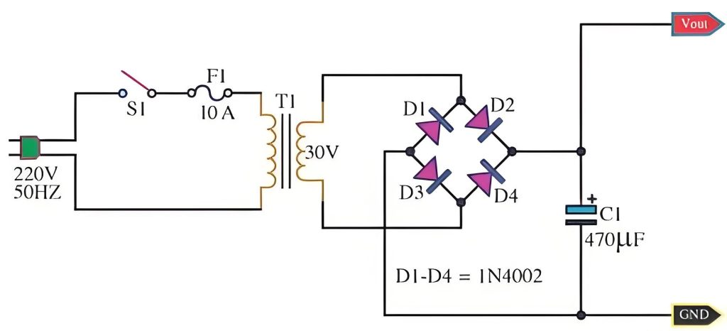
The current fuse in position F1 is usually connected in series with the line.
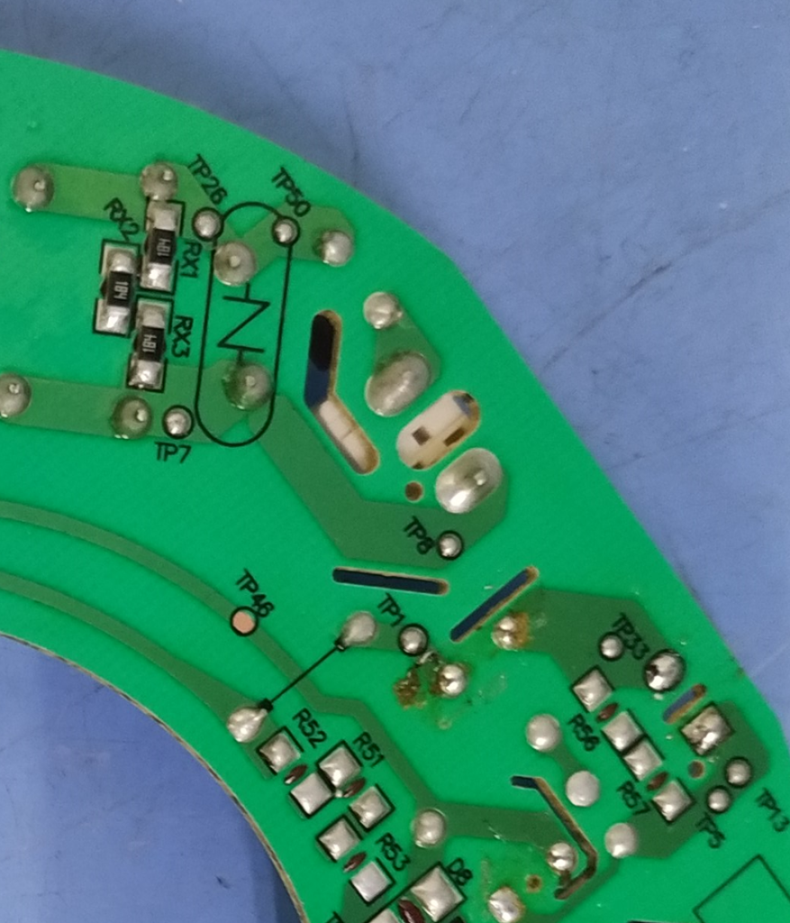
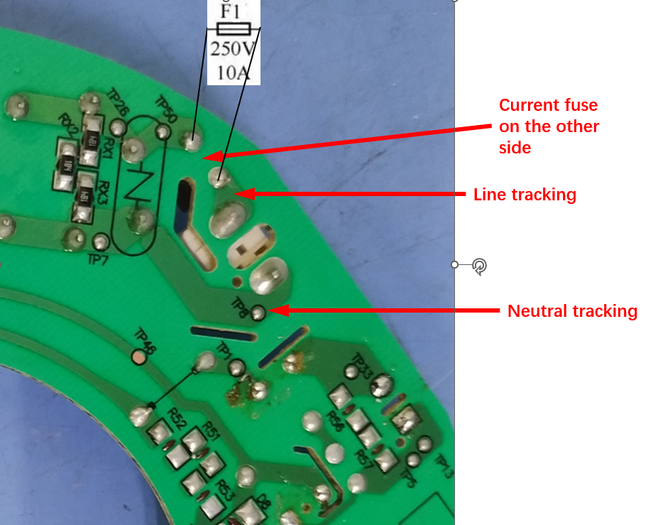
The photos of the real thing are shown in the following two pictures, the left one is not labeled, the right one shows the location of the current fuse and some other basic information.

In the diagram above, there is definitely functional insulation between line tracking and neutral tracking, as we have explained in the definition of functional insulation.
So is there functional insulation at the ends of the current fuse? Here you need to measure the distance between two locations, firstly on the front side of the board, on the body of the current fuse, and secondly between the tracking on the board, e.g. as indicated by the black text in the picture above.
Normally, the two ends of a current fuse are insulated, although internally they are connected together. When the internal fuse is broken, the insulated ends are necessary to break the circuit too. In order to ensure that the circuit breaks after the current fuse has broken, it is assumed that there is functional insulation, while the clearance of functional insulation is relatively easy to meet, the creepage distance sometimes does not meet the requirements of the standard, especially in the case of Pollution degree 3.

I think there is no functional insulation here. According to the definition of functional insulation, there needs to be a different potential, and there is no different potential between the two ends of the current fuse under normal operation, so there is no functional insulation under normal operation. When the current fuse is broken, it will appear at both ends of the potential difference, theoretically, there is functional insulation. However, when the current fuse broken and the electrical product does not work properly, it is at least in a non-normal operating condition, and the cause of the current fuse broken is the abnormal operation test from clause 19. According to clause 19.13 of the standard, after the abnormal test need to carry out electrical strength test, the test voltage of functional insulation is twice the working voltage, and there is no requirement for creepage distance and electrical clearance. It might be thought that the accumulation of contamination at the ends of the blown fuse would lead to a short-circuit in the functional insulation, but since the current fuse is broken, there is also the accumulation of contamination, which accumulates very slowly when the appliance is not in operation and no forced convection air can be supplied.
Therefore, when the appliance is in normal operation, there is no functional insulation; when the current fuse broken, it is sufficient to take into account the electrical strength test of clause 19.13, and it is not necessary to measure and evaluate the clearance and creepage distance of the functional insulation.
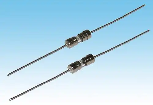
For reference, the following figure shows a physical drawing of the appearance of a current fuse.

Similar Posts

  • 第3項「基礎断熱」の定義の見方

    基本絶縁: 感電に対する基本的な保護を提供するために通電部分に適用される絶縁 一般的に言えば、充電部と直接接触する絶縁層は、一般的な絶縁材料 (PVC や ABS などのプラスチック材料など) である場合もあれば、空気または絶縁層上に形成された距離 (沿面距離) である場合もあります。断熱材の表面。ほとんどの国では、ユーザーが基礎断熱材に触れる可能性のある構造は認められていません。したがって、基礎絶縁は通常、機器の内部に配置されており、通常の動作中に触れることはできません。 下の左の写真は扇風機の底カバーの写真、右の写真は底カバーを外した写真です。右の写真の電源コード内の青と茶色のワイヤ外皮は、基本絶縁と考えることができます。同時に、黒いシェルに接続されているスイッチの白、赤、黒の線の外皮も基礎絶縁であると判断できます。ここでの充電部分は、ワイヤ内の銅芯です。また、スイッチ内の金属導体と白色シェル内面との距離により基礎絶縁性と判断できます。沿面距離の観点から見ると、スイッチ内の導体の電気は、スイッチの絶縁表面に沿って白いシェルの内面 (右の図の左の小さい角) まで伝導 (登って) します。この距離は、基礎絶縁体の沿面距離とみなしてください。電気的クリアランスの観点からは、スイッチ内部の導体の電気はファンボトムカバー内面とスイッチシェルの間の空気を介して直接伝導しており、この空気間の距離が基礎絶縁のクリアランスと判断されます。 (白いプラスチックシェルは追加絶縁と判断されます) 下図に示すように、モーターの巻線のラッカー塗装された導体は、モーターのステーターに挿入された白いスロット紙によって固定されています。巻線は規格により露出充電部として識別されます。ラッカー塗装された巻線の導体とモーターのステーターは、スロット ペーパーを介して導電ループを形成します (一般に、クラス I 機器の場合、モーター ハウジングが接地されているため、モーター ハウジングに接続されているステーターも接地されます。クラス II 機器では、モーター ハウジングとモーター ステーターは接地されていない中間金属コンポーネントです)。スロット紙の導電性は十分ではありませんが、スロット紙には微弱な電流が発生します。ここで発生する電流量はスロット紙の性能に直結します。ここでのスロット紙の材質は基礎絶縁体と判断できます。スロット ペーパーの表面は巻線の金属積層板に接続できるため、スロット ペーパーの表面上の距離は基礎絶縁体の沿面距離として決定できます。スロットペーパーの材質自体が固体絶縁の役割を果たします(固体絶縁には厚さの要件はありませんが、それでも第 13 章と第 16 章の漏れ電流と耐電圧要件を満たす必要があります)。したがって、上図の電気的クリアランスは、空中での巻線と固定子の積層間の最短距離です。 下の図に示すように、注意: モーターの巻線が適切に固定されておらず、モーターのステーターに非常に接近しています。第 29 条の沿面距離と空間距離の要件を満たすことができなくなりました。これは一般的な不適合項目です。 ファンモーターの基礎絶縁 basic insulation of fan motor

  • IEC 60335-1の表17および表18

    表 17 と表 18 には、「動作電圧と gt; 10 V および ≤ 630 V については、電圧が表に指定されていない場合、沿面距離の値は補間によって求められる場合があります。」という注記があります。 動作電圧が表に記載されている値ではない場合、通常は制限値を取得するために計算する必要があります。便宜上、Excel テーブルを用意しました。テスターはテーブルを直接クエリして、対応する制限値を取得できます。 ダウンロード

  • 第 3 項 – 「クリアランス」の定義の理解方法

    クリアランス: 2 つの導電性部品間、または導電性部品と導電性部品間の空気中の最短距離アクセス可能な表面。 クリアランスは非常に重要な概念です。クリアランスを理解するには、完全に絶縁された物質はなく、空気も電気を通すことができるということをもう一度言う必要があります。電圧が非常に高い場合、電流は空気中に伝導します。雷雨時の落雷は、雷が空気中を伝導する典型的な例です。雷の電圧は非常に高いため、空気の非常に長い部分を突き破り、空気のこの部分が導電性になります。家電製品では、電圧は非常に低いですが、製品中には空気が多く含まれており、空気中にも電流が流れます。電圧が増加すると、電圧が空気を突き抜ける距離も長くなります。これにより、クリアランスの概念が生まれます。クリアランスの詳細な説明については、IEC 60664-1 (低電圧システム内の機器の絶縁調整 – パート 1: 原則、要件、およびテスト) を参照してください。 次の写真は電気的除去の経路をよく説明していると思います。 電圧の異なる2つの電極間や、充電部と電気製品使用者の手の間に隙間が生じる場合があります。上の写真の 2 つの電極を他の物体として想像するだけで済みます。 キー アクセス可能な発掘された金属部品 1 つ 2筐体3 接地されている金属部分4 出土した接近不可能な金属部分活電部 L1 と L2 は互いに分離されており、一部は開口部を備えたプラスチックの筐体で囲まれ、一部は空気に囲まれ、固体絶縁体と接触しています。構造内部にはアクセスできない金属が組み込まれています。金属カバーが 2 つあり、そのうちの 1 つはアースされています。絶縁クリアランスの種類基礎絶縁L1A L1D L2F 機能性絶縁体L1L2 補助絶縁DE FG 強化絶縁 L1K L1J L2I L1C 注記隙間 L1D または L2F が強化絶縁の隙間要件を満たしている場合、補助絶縁の隙間 DE または FG は測定されません。 L1CNOTE If the clearances L1D or…

  • |

    If the PCB is sealed with solid sealant, how to determine the creepage distance and clearance?

    functional insulation as well as other insulation exists on circuit boards. Typically, the surface environment of a circuit board is determined to be either Pollution degree 3 or pollution degree 2.If the circuit board is mounted in an electrical box and sealed with a solid sealant, the sealing will look as follows: What should be…

  • 第3項「機能絶縁」の定義の見方

    機能的絶縁: 電位の異なる導電性部分間の絶縁であり、機器が適切に機能するためにのみ必要です。 下の図は典型的な機能絶縁の図です。PCB の銅レール層の図に示されているように、ラベルの茶色の部分は電源活線 (電流ヒューズ間に接続されている 2 つの茶色の位置)、青色の部分です。接続は電力線の中性線であり、活線であり、中性線には 2 つの線の間に電圧差があるため、選択した銅線レールの青色の部分と選択した銅線レールの茶色の部分の間の最短距離になります。レール、つまり機能絶縁体です。実際、通常の動作では、下の写真の回路基板、銅レール上の電圧は多くの場所で同じではないため、機能絶縁の形成により、読者は動作電圧によって独自の回路分析を行うことができます。各部分。 AC 非同期モーターの一般的な巻線接続図は次の図のようになります。図のコンデンサが動作しているとき、コンデンサの両端の電圧は通常、製品の定格電圧よりも高くなります。たとえば、定格電圧が 220V の場合、動作中にマルチメータで測定されるコンデンサの両端の電圧は通常 300V を超えます。このとき、コンデンサの両端間の機能絶縁を評価する場合、300V以上の使用電圧を基準に評価する必要がありますが、実際にはコンデンサ自体の機能絶縁は一般的には可能ではありません。コンデンサの端子がコンデンサのケース内に封入されているため測定されます。測定できる箇所はコンデンサの2本のリード線の端子台です。 下図に示すように、端子台には左側に活線が接続され、右側に中性線が接続されています。赤い線の位置は機能絶縁体の沿面距離です(クリアランスもここで決定できます)。 下の図に示されているキャリパーの測定値は、PCB 上のアダプターの入力のライブ銅線と中性銅線の間の機能絶縁を表しています。 As shown in the figure below, the terminal block has the live wire connected on the left and the neutral wire connected on the right. The position of the red line is the creepage distance of the…

  • How are the creepage distances and electrical clearances of PTC heating element surfaces determined?

    We are discussing here the second structure of the PTC heating element, PTC heating element structure please refer to the explanation of its definition. How is the creepage distance of the functional insulation at the location of the red circle in Figure 1 determined? We all know that NOTE 1 of TABLE 18 section has…