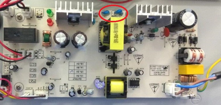
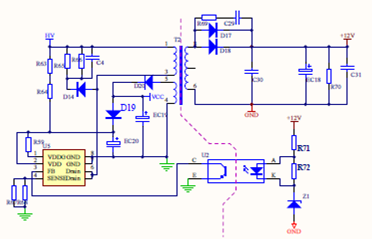
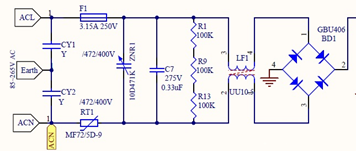
規格の定義から、保護インピーダンスは接地が存在するクラス II 構造で使用されます。ここでの接地が保護接地として定義されている場合、保護インピーダンスはクラス II 構造で使用され、ここではクラス I 構造であるため、明らかに CY1 と CY2 を保護インピーダンスとして定義できません。ここでの接地が機能接地として定義されている場合、2 つの問題があります。まず、これはクラス I 構造であるため、CY1 と CY2 は保護インピーダンスとして定義できません。次に、クラス II 構造の場合、CY1 と CY2 を保護インピーダンスとして定義でき、保護インピーダンスの関連要件を満たす必要があります。私の個人的な意見は、CY1 と CY2 は保護インピーダンスではなく、直接基礎絶縁とみなしてよいと考えています。結局のところ、回路図に示されている設計は規格に受け入れられないということでしょうか?そしてnbsp;
From the definition of the standard, the protective impedance is used in the class II construction, where there is earthing. If the earthing here is defined as protection earthing, then obviously, CY1 and CY2 cannot be defined as protection impedance, because protection impedance is used in class II construction, and here is class I construction. If the earthing here is defined as functional earthing, then there are two problems. First, this is a class I structure, then CY1 and CY2 cannot be defined as protection impedance. Second, if it is a class II structure, CY1 and CY2 can be defined as protection impedance, and then the relevant requirements of protection impedance need to be met. My personal opinion is that CY1 and CY2 are not protective impedances, and we can directly regard them as basic insulation. At the end, in other words, the design shown in the circuit diagram is not accepted by the standard?
If they are protective impedances, then which is need to comply with clause 22.42 – “Protective impedance shall consist of at least two separate components.”.
fixed appliance: appliance that is intended to be used while fastened to a support or while secured in a specific location. The definition emphasizes fastening to a bracket or fixing in a specific position. Generally, we think that this kind of fixation requires some installation actions and some fixing devices, these devices can be fixed…
all-pole disconnection: disconnection of both supply conductors by a single initiating action or, for multi-phase appliances, disconnection of all supply conductors by a single initiating actionNOTE For multi-phase appliances, the neutral conductor is not considered to be a supply conductor. Single-phase power: An AC power system composed of one live wire and one neutral wire.Three-phase…
detachable part: part that can be removed or opened without the aid of a tool, a part that is removed or opened in accordance with the instructions for use, even if a tool is needed for removal, or a part that does not fulfil the test of 22.11.NOTE 1 If for installation purposes a part…
heating appliance: appliance incorporating heating elements but without any motor. Before introducing this definition, we need to briefly introduce the electric heating elements commonly used in household electrical appliances. PTC heating element: PTC (Positive Temperature Coefficient) heating elements are widely used for various heating applications because of their self-regulating properties and safety features. Here are…
accessible part: part or surface that can be touched by means of test probe B of IEC 61032, and if the part or surface is metal, any conductive part connected to it.NOTE Accessible non-metallic parts with conductive coatings are considered to be accessible metal parts. There are some parts or surfaces in the appliance that…
protective electronic circuit: electronic circuit that prevents a hazardous situation under abnormal operating conditions.NOTE Parts of the circuit may also be used for functional purposes. With the advancement of technology, more and more electronic circuits are being used in household electrical products, and these electronic circuits are usually integrated on PCBs. They use microprocessor chips…