Clause 3 – How to understand the definition of “protective extra-low voltage circuit”
protective extra-low voltage circuit: earthed circuit operating at safety extra-low voltage which is separated from other circuits by basic insulation and protective screening, double insulation or reinforced insulation
NOTE 1 Protective screening is the separation of circuits from live parts by means of an earthed screen.
NOTE 2 A protective extra-low voltage circuit is also known as a PELV circuit.
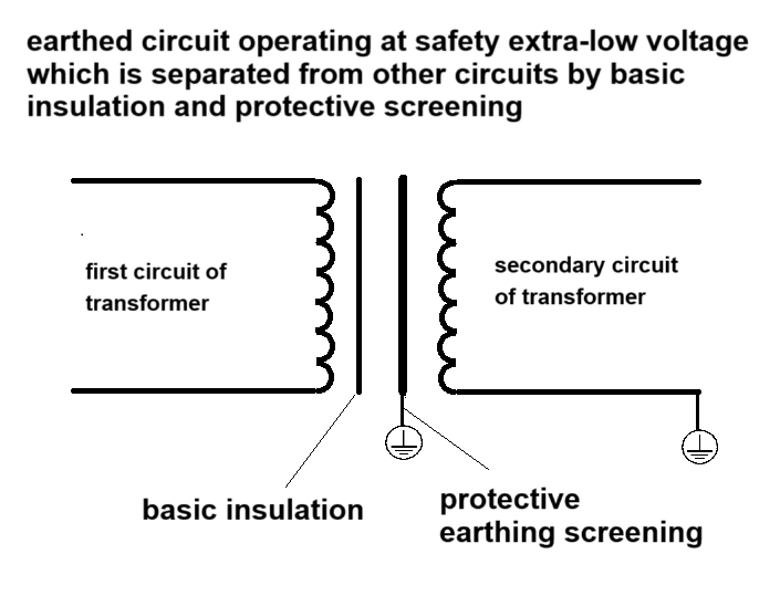
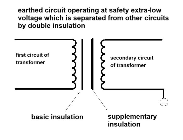
The definition of this term mentions earthed circuit operating at extra-low voltage. There is controversy over the understanding of this definition. The first view is that if the secondary circuit of the transformer is directly connected to the protective earthing, the secondary circuit can be determined to be PELV. The second view is that the secondary circuit of the transformer needs to pass through a protective impedance or additional insulation before it can be connected to the protective earthing circuit, which is considered PELV. I personally support the first view.
Let me first introduce how I came to my point of view. In the case of not knowing the intention of the standard, we can indirectly deduce the intention of the standard based on the definition and requirements of a certain concept (PELV) in several versions of the standard. There is no definition of PELV in the third edition of the IEC 60335-1 standard. PELV was added in the fourth edition of the standard. There are two requirements for PELV. The first is the fourth paragraph of 27.1 of the standard, which requires “Safety extra-low voltage circuits shall not be earthed unless they are protective extra-low voltage circuits.” The standard believes that PELV can be grounded (it does not say whether it is directly or indirectly grounded). In the default principle of the entire IEC 60335-1, the external protective earthing circuit is a circuit that is allowable to be touched by the user and is not a circuit that is dangerous for electric shock. Therefore, 27.1 actually has no purpose. The requirement of clause 27.1 is to reduce the earthing requirements of SELV, so the definition of PELV is given. Second, there is a exception for exemption from earthing resistance testing for PELV circuits in 27.5. Therefore, it is reasonable to believe that the definition of PELV does not have a practical safety protection function. At the same time, the requirements of clause 22.59 of the sixth edition of the standard are also mainly for transformers with two separate secondary circuits, and some isolation is required between these two secondary circuits.
Here we need to explain that the sixth edition of the standard changed SELV to ELV in the definition of the wording, which is not a relaxation of the requirements. It is correct to change SELV to ELV because the definition of PELV has emphasized that ELV is isolated by double insulation (basic insulation and protective screening, double insulation or reinforced insulation), so there is no need to repeat the requirement of SELV.
Next, let me explain the views of different points of view.
First, the fourth paragraph of 27.1 does not specify how the PELV circuit is grounded. It can be directly grounded or grounded after protective impedance or supplementary insulation. Then, the IEC 60335-1:2020 ED6.0 version added the requirements of clause 22.59, as follows: Protective extra-low voltage circuits shall be separated by at least supplementary insulation from circuits operating at safety extra-low voltage. There are two ways to understand 22.59. One is that SELV has supplementary insulation before grounding to prevent the current on the protective earthing from flowing back into the circuit, causing the risk of electric shock. After all, there is an electric charge on the earth. In some special cases, if the potential of SELV is lower than the potential of the earth, this will form a conductive loop and cause the risk of electric shock. The second situation is that the isolation transformer has two secondary windings, one of which is a SELV circuit, but because it does not comply with clause 8.1.4, it is not allowed to be touched, and the other secondary winding corresponds to PELV, which can be touched. In this way, the purpose of clause 22.59 is to ensure that the two independent secondary windings of the transformer (the two independent windings are PELV and SELV) do not affect each other. According to the first understanding of clause 22.59, combined with the understanding of 27.1 that it cannot be directly grounded, we can conclude that SELV can only be determined as PELV after being grounded through an additional insulation.
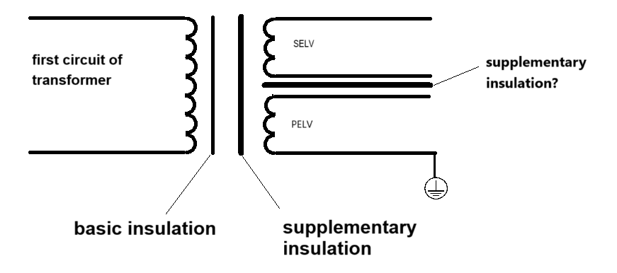
What I personally question is whether it is necessary to consider the situation where the current is generated between the external protective earthing circuit and the internal circuit of the appliance due to the influence of the internal circuit of the appliance. In conventional products without SELV or PELV circuits, there is basic insulation between the live parts and the protective earthing circuit. Does the standard believe that this basic insulation can prevent the dangerous current between the protective earthing circuit and the internal live parts? If the answer is yes, then clause 22.59 should require basic insulation instead of additional insulation. Of course, the standard may also increase the requirements for PELV circuits, regardless of the basic anti-electric shock protection rules of class I appliances. According to common sense, the PELV circuit is already a circuit generated by isolation transformer isolation, so why is there an isolation requirement for additional insulation? What kind of electric shock risk is isolated by the additional insulation here?
IECEE has made many decisions on PELV and functional earthing, such as DSH-492, CTL PDSH 2244, CTL-OP 106.
In addition, IECEE decision – DSH-492 has the following two pictures.
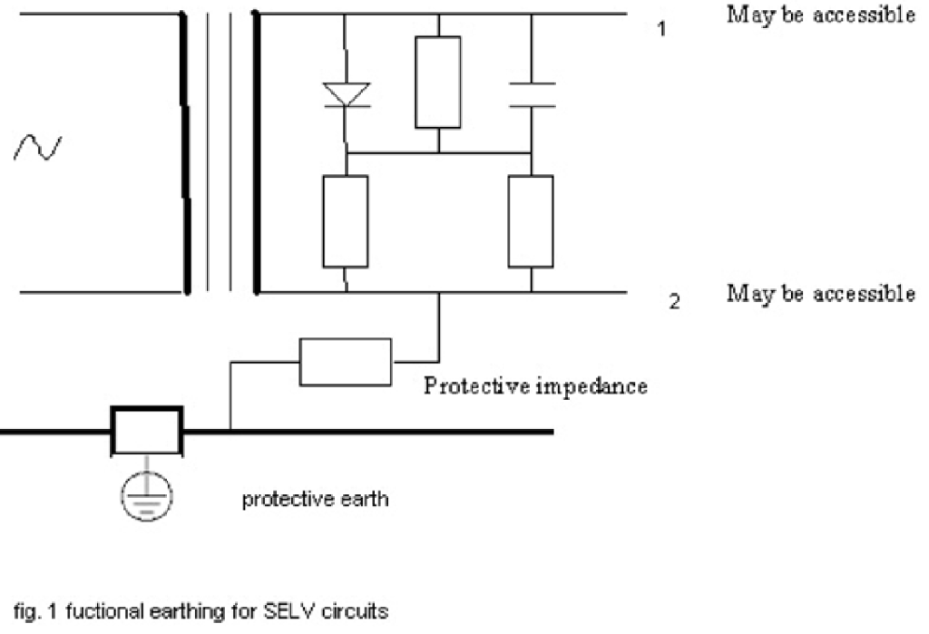
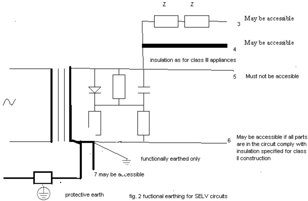
To be honest, I don’t understand the meaning and basic principles of these two pictures. I personally think that even if we understand the basic principles of this picture, we cannot make a judgment based on this principle, because this decision is only for the third edition of IEC 60335-1.
In addition, IECEE decision – OSM/HA 75 also mentions the requirements of PELV, and interested readers can read it.
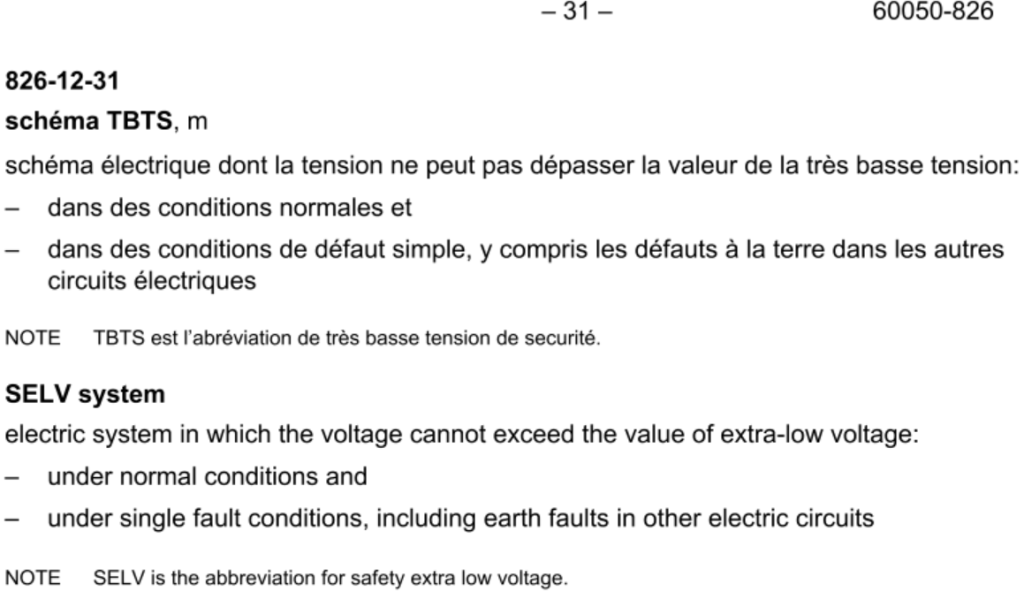
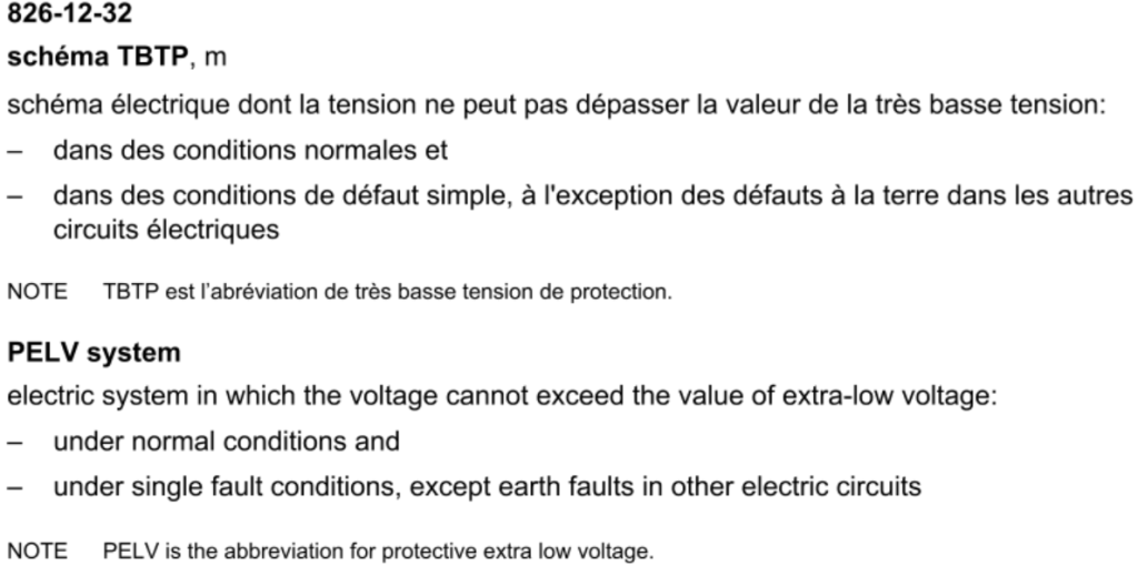
According to the definition of SELV and PELV in IEC 61140 standard:
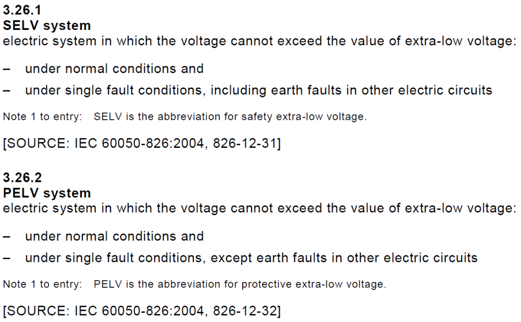
There is no requirement for earthing failure of PELV, so accordingly, the grounding measures of PELV are considered reliable by the standard.
Note 1: The protective shield is to isolate the circuit from the live parts by means of a grounded shield.
Note 2: The protective extra-low voltage circuit can also be represented by the PELV circuit.
SOURCE: IEC 60050-826 regarding to SELV and PELV as below: