Clause 3 – How to understand the definition of “PTC heating element”
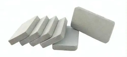
PTC heating element: element intended for heating consisting mainly of positive temperature coefficient resistors that are thermally sensitive and have a rapid non-linear increase in resistance when the temperature is raised through a particular range.
As the temperature increases, the resistance of the heating element of the PTC heating element increases. The relationship between temperature and resistance is positively correlated.
PTC heating element is widely used in household appliances, such as hairdryers, electric blankets, electric irons, air conditioners, hot air curtains, dehumidifiers, dryers, clothes dryers, room heaters and other devices that need to provide warm air, which utilize the autostatic characteristic of the PTC element for heating.
He has some of the following characteristics
- automatic constant temperature: PTC heating element can automatically adjust the power output according to the changes in ambient temperature to maintain a constant temperature without additional temperature control devices.
- Safe and stable: PTC material has strong high temperature resistance and can maintain constant temperature at the set temperature, which is safe and reliable and reduces the risk of overheating.
- long life, no noise: because there is no mechanical wear and tear or arc generation, PTC heating element will not produce noise, and long service life.
- Rapid temperature rise: PTC material has excellent thermal conductivity, which can quickly reach the working temperature and improve the heating efficiency.
- High thermal efficiency: PTC heating element has high thermal efficiency, which can effectively convert electrical energy into heat energy and reduce energy loss.
- Wide voltage range: PTC heating element can work in a wide range of voltage, from 12V to 380V can be designed according to the need.
- Flexible design: PTC heating elements can be designed into different power and shape as needed to suit different applications.
- Non-combustible, safe and reliable: PTC heating elements do not produce open flame when working, reducing the risk of combustion and fire.
- Self-control of temperature in case of fan failure: In applications requiring fan cooling, if the fan stops working, the power of the PTC heating element will be automatically reduced to prevent overheating.
- Energy saving and environmental protection: PTC heating element can automatically adjust the power according to the ambient temperature to optimize power consumption and achieve energy saving.
- Small impact of changes in operating voltage: even if the operating voltage changes are large, the surface temperature of the PTC heating element changes are very small.
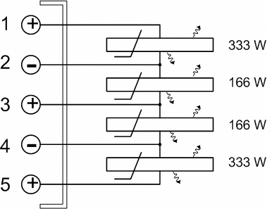
- more PTC heating elements used together, should be connected in parallel, not in series: to ensure that each element can be independently controlled and regulated.
- Different heat dissipation conditions make the heating power of the PTC heating element varies greatly: the faster the heat dissipation is stabilized, the greater the power; PTC surface temperature is higher, the higher the power.
- The surface temperature of the PTC heating element is controlled by the PTC itself: it can also be controlled by disconnecting the circuit, but not by regulating the voltage to control the surface temperature.
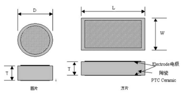
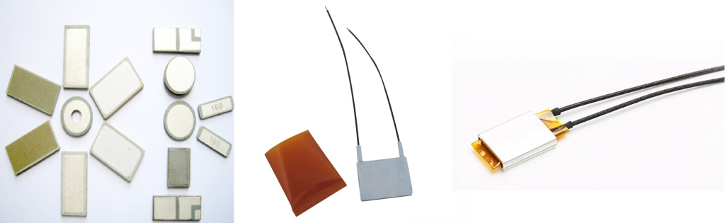
PTC heating element mainly consists of three parts, ceramic heating element, heat sink, and conductive glue, but in the regular case, insulating structural glue will be used. In the case of a PTC heating element with a heat sink structure, there are usually two structures. (Here we will not discuss the PTC heating element without heatsink structure, because its power is very small).
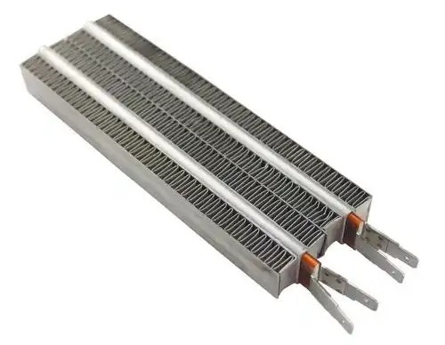
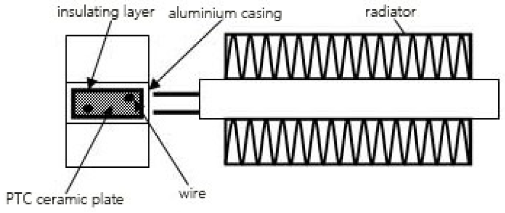
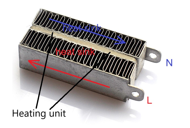
The first one will wrap the ceramic heating element with high-temperature insulating paper, and then the outer layer of the high-temperature insulating paper will include the aluminum shell, and then the heat sink will be glued to the two sides of the aluminum shell. As shown in the picture below.
The PTC heating element consists of three main parts, the ceramic heating element, the heat sink, and the conductive glue, but in the regular case, an insulating structural glue is used. In case of PTC heating element with heat sink structure, there are usually two structures. (Here we will not discuss the PTC heating element without heatsink structure, because its power is very small).
The first one will wrap the high temperature insulation paper on the ceramic heating element, then wrap the aluminum shell on the outer layer of the high temperature insulation paper, and then the heat sink will be glued on both sides of the aluminum shell. As shown in the picture below.
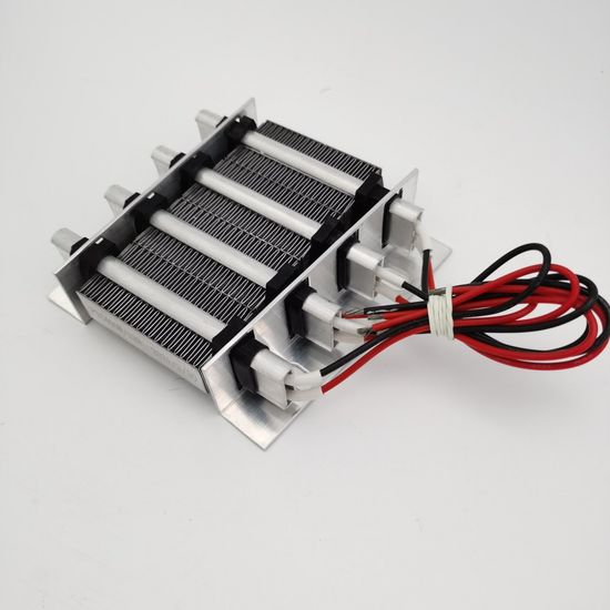
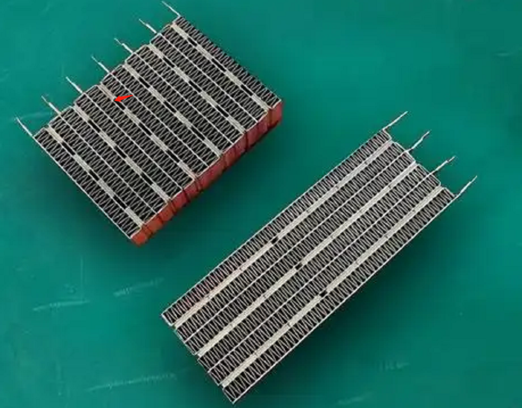
The second structure will be the heatsink and ceramic heating element through the conductive glue directly bonded together, if there is a gap between the heatsink, the gap may be filled with insulating structural adhesive. As shown in the figure below
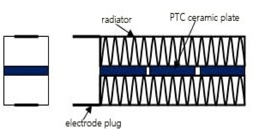
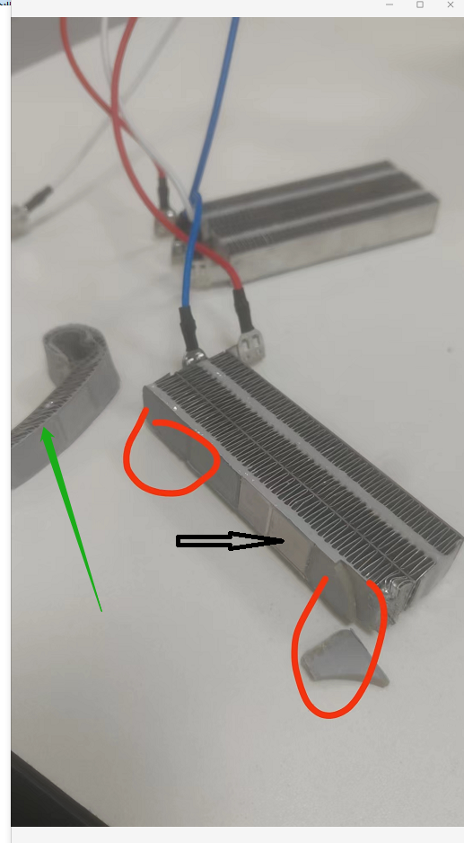
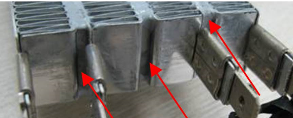
The parts indicated by the green arrows are the disassembled heat sinks, and the location selected by the red circle is the structural adhesive, which is insulating and whose main purpose is to connect the heat sinks and fill the gap between the two heat sinks, making the overall structure of the PTC heating element solid. The position indicated by the black arrow in the center is the heating unit. It is a conductor made of ceramic, the higher the temperature, the higher the resistance. The two large surfaces of the heating element are coated with a conductive glue to connect and fix it to the heat sink.