Clause 3 – How to understand the definition of “live part”

live part: conductor or conductive part intended to be energized in normal use, including a neutral conductor but, by convention, not a PEN conductor
NOTE 1 Parts, accessible or not, complying with 8.1.4 are not considered to be live parts.
NOTE 2 A PEN conductor is a protective earthed neutral conductor combining the functions of both a protective conductor and a neutral conductor.

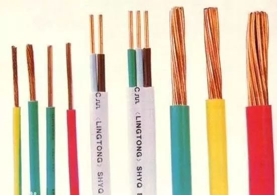
In normal use (except abnormal use and for the protection of action) energized conductor and conductive parts. Conductor is easier to understand, as shown in the figure below, which is wrapped in copper conductor parts is live part.

The other part of the conductor that is energized can be a terminal, which can be an electrically powered component, such as a PTC heating element, a winding in a motor, a tungsten filament in a light bulb, a heating wire in a heating tube, and so on. Electrical products are energized in order to achieve the function for which they are designed, usually through the utility power supply. Normal utility power can cause electric shock, so the conductors in an appliance can be defined as live parts.
However, if the utility power is transformed to reduce the voltage, current and other values, then they may become conductors without electric shock damage. We know that ordinary household dry batteries are just no risk of electric shock, and some adapters, their outputs are just no risk of electric shock. For such conductors on circuits with low voltage and current, the standard considers them not to be live parts, but they need to be tested according to clause 8.1.4 of the standard to confirm whether they are live parts.
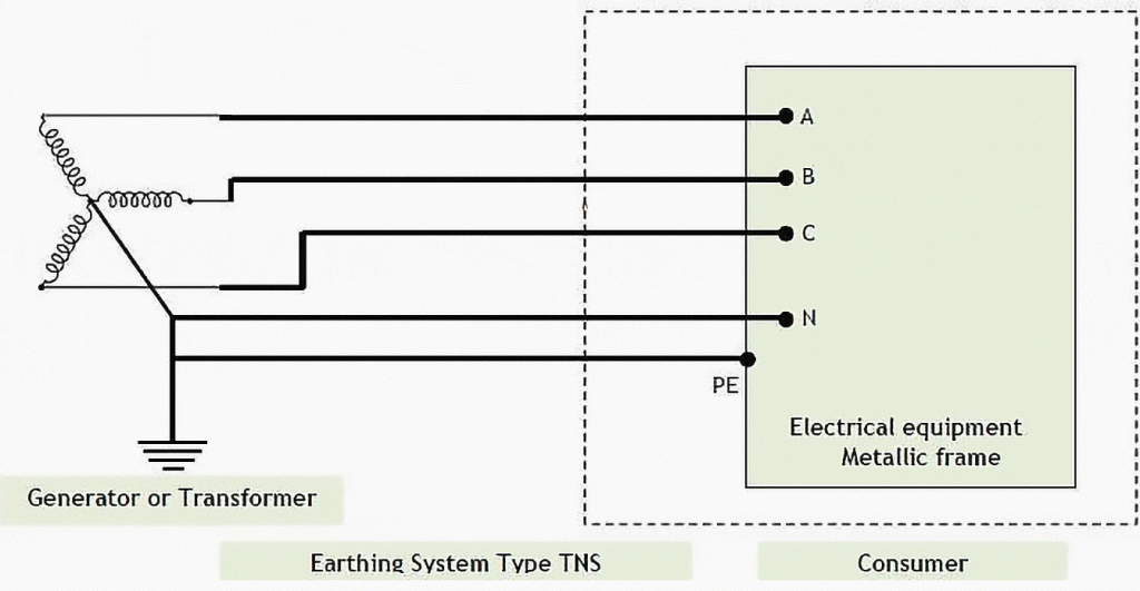
The conductor of the protective earthing is not a live part, but the neutral conductor is a live part, for example, in the following diagram of TN-S system, the conductors of A, B, C, N are all live parts, but PE (actually PEN) is not a live part, although we can see in the diagram that N and PE are connected together.

However, if the single-phase apparatus corresponds to the TN-S system, as follows

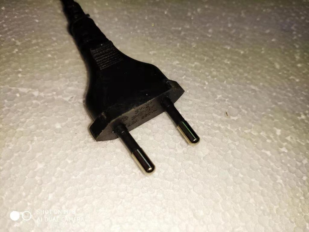
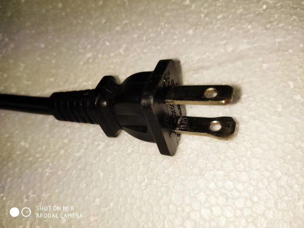
In many countries, while the socket-outlet can distinguish between L and N wires, the plug cannot distinguish between L and N wires, and therefore N is considered to be the Live part. the photo of the two plugs below illustrates the problem. The photo on the right is the plug with the polarity feature used in the US.

Similar Posts

  • 第 3 項 – 「クラス 0 アプライアンス」の定義の理解方法

    クラス 0 機器: 感電に対する保護が基礎絶縁のみに依存しており、導電性のアクセス可能な部品があったとしても、設備の固定配線内の保護導体に接続するための手段がなく、万一の場合に信頼できる機器。環境に設置された基礎断熱材の欠陥。注記 クラス 0 機器には、基礎絶縁の一部または全体を形成する絶縁材料のエンクロージャ、または適切な絶縁によって充電部から分離された金属エンクロージャのいずれかが備えられています。絶縁材の筐体を備えた機器に内部部品を接地するための設備がある場合、それはクラス I 機器またはクラス 0I 機器とみなされます。 この種の機器には保護接地装置がなく、同時に充電部を絶縁層で 1 層だけ包むか、絶縁層を使用して使用者を充電部から隔離します。ほとんどの国ではクラス 0 のアプライアンスを受け入れません。クラス 0 機器を受け入れられるのは、主電源電圧 (定格電圧) が日本などの 100 V と米国やメキシコなどの 120 V の一部の国だけです。ここで、同じ入力電力を達成するためには(たとえば、定格入力電力が 3000W のルームヒーター)、定格電圧が低いほど、対応する動作電流が大きくなることに言及する必要があります。逆に、定格電圧が高いと、それに対応する入力電流は小さくなります。大電流の場合、製品内の通電部品の発熱がより深刻になり、火災の可能性も高まるため、防火要件がより厳しくなります。低電流高電圧の場合、通電部の発熱はそれほど深刻ではありませんが、高電圧のため絶縁破壊の可能性が高くなり、感電防止の要件がより厳しくなります。 IEC 60335 シリーズの規格には、感電に対する保護に関して非常に高い要件が定められているのはこのためです。 IEC 60335 規格の主な作成者は、定格電圧 220 ~ 240V の国の専門家です。一方、米国の UL シリーズ規格には防火に関するさらに厳しい要件があります。通常、全ての充電部を基礎絶縁のみで保護するような機器は存在しません。感電に対する保護測定のほとんどは、二重絶縁または強化絶縁の要件を満たすことができるのが一般的です。もちろん基礎絶縁+接地保護構造もございます。一般的な状況は、電源コードのワイヤ シースが 1 層だけであり、デバイスの保護レベルは電源コードの基本絶縁、つまり最低の保護レベルのクラス 0 によって決まります。 次の 2 つの図は、クラス 0 アプライアンスの電源コードの情報を示しています。 1 つは回路図を示し、もう 1 つはプラグ付きの電源コードを示します。 次の図は、クラス…

  • Clause 3 – How to understand the definition of “non-detachable part”

    non-detachable-part: part that can only be removed or opened with the aid of a tool or a part that fulfils the test of 22.11. The definition of this concept is mainly for the judgment of clause 8 and clause 20, and the judgment of other clauses may also be used. On the appliance, whether any…

  • 第3項 「第二種工事」の定義の見方

    ここで重点を置くのは、二重絶縁または強化絶縁の要件を満たすことができる機器の構造の一部です。したがって、クラス I アプライアンスにはクラス II 構造も含まれます。例:下図のオーブンでは金属シェルとプラスチック製スイッチノブが使用されています。使用者がスイッチノブに触れると、ノブは絶縁体でできているため接地できません。感電に対する保護はノブ自体の絶縁にのみ依存します。スイッチ内部の充電部とスイッチノブ軸間は基礎絶縁となっており、スイッチノブは補助絶縁を形成します。したがって、スイッチノブの位置はクラスII構造となります。    

  • A question about whether the second part of clause 21.2 needs to be tested.

    We know that clause 29.3.2 and clause 21.2 are two separate clauses and they are not very much related, which means that the product being assessed needs to fulfill both clauses if applicable.A reinforced insulation system consisting of three separate layers of insulating material or what could be considered a double insulation system, Each layer…

  • 第3項「補助絶縁」の定義の見方

    補助絶縁:基礎絶縁が切れた場合に感電を防ぐために、基礎絶縁とは別に施される独立した絶縁 基礎断熱材の外側にあり、基礎断熱材から独立しており、通常はユーザーがアクセスできる断熱材。補助絶縁はその名のとおり追加的なものであり、基礎絶縁に追加する絶縁を指します。これには、この規格の基本原則、つまり二重保護の原則が関係します。いかなる危険に対しても、少なくとも 2 層または 2 セットの保護措置を講じる必要があります。いずれかの保護手段が失敗した場合でも、アプライアンスは別の保護層によって保護されます。ここでの追加絶縁の要件は、基礎絶縁が機能しなくなった場合に保護の役割を果たすことができる絶縁を考慮することです。ここでの保護は充電部の保護のみを目的としています。この規格の他の要件には、非充電部分に対する二重保護措置の要件が含まれます。 下図に示すように、基礎絶縁体の外表面(ここでは内部電線の電線被覆の外表面、またはスイッチのプラスチック材料表面と理解してください)から絶縁可能な箇所まで使用者が触れる部分(機器の底カバーや側面シェル)は、写真例から、機器の底カバーや側面シェルが補助絶縁材であると判断できます。これに対応して、サイドシェル内面に沿った内部リード線シースから外部ユーザーが触れる可能性のある場所までの沿面距離を補助絶縁とし、内部基礎絶縁からの最短直線距離と定義できます。空気を通って外部ユーザーが触れる可能性のある場所までの距離を補助絶縁クリアランスとして定義できます。ここでいうクリアランスとは、一般的にボトムシェルとサイドシェルの間の隙間を指します。

  • A question about clause 21.1 and detachable parts

    21.1 Appliances shall have adequate mechanical strength and be constructed to withstand such rough handling that may be expected in normal use.Compliance is checked by applying blows to the appliance in accordance with test Ehb ofIEC 60068-2-75, the spring hammer test.The appliance is rigidly supported and three blows, having an impact energy of 0,5 J,…