Clause 3 – How to understand the definition of “accessible part”

accessible part: part or surface that can be touched by means of test probe B of IEC 61032, and if the part or surface is metal, any conductive part connected to it.
NOTE Accessible non-metallic parts with conductive coatings are considered to be accessible metal parts.

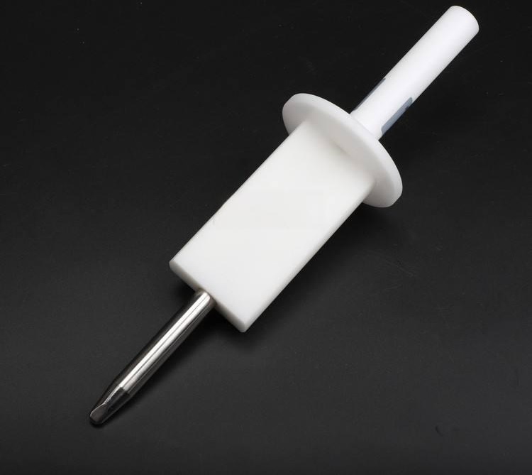
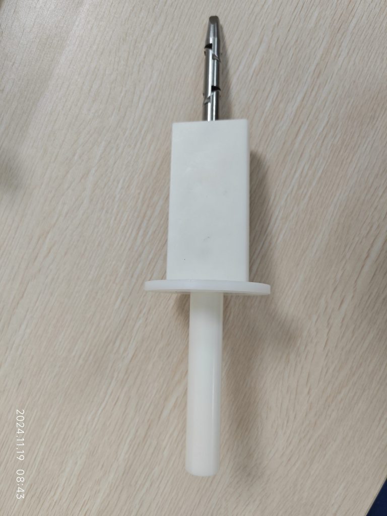
There are some parts or surfaces in the appliance that is not allowed be touched or be accessible, the reason for this may be high temperature, may be electrically charged, or there may be mechanical injuries, such as the movement of the fan blade. The smallest part of the human body that can touch other objects is the finger, but different people’s fingers are different, so the standard here stipulates a fixed size of the finger, finger size in accordance with the standard IEC 61032 in the type B finger. The following figure

It is also important to note here that if the part touched by the tested finger is metal, because metal conducts electricity, then parts such as those touched by metal parts are considered electrically accessible. In practice, the requirement that metal parts may be electrically conductive does not need to be taken into account when determining injuries to moving parts.

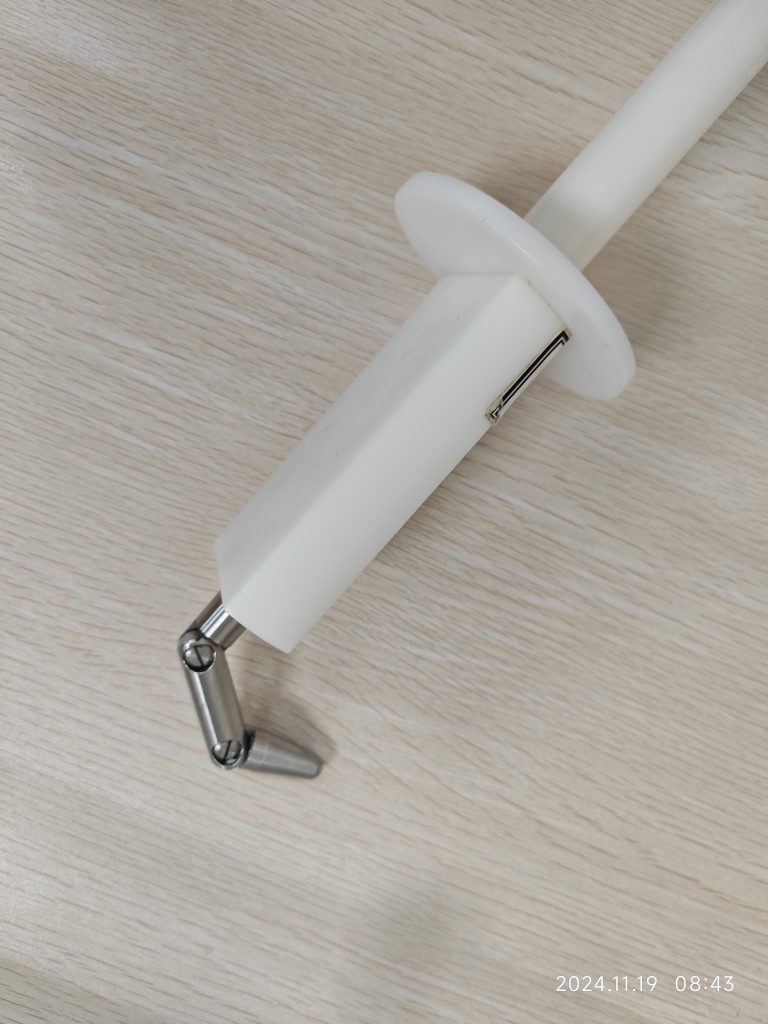
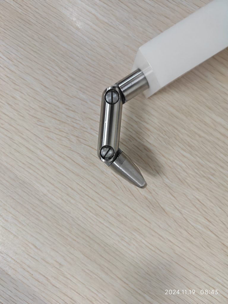
Type B test probes have a design that is without joints. Typically, standards will require that a test finger without joints be used first, followed by a test finger with joints. The exact method of inspection is discussed in clause 8.

Similar Posts

  • 4 General Requirement

    4 General Requirement: Appliances shall be constructed so that in normal use, they function safely so as to cause no danger to persons or surroundings, even in the event of carelessness that may occur in normal use.In general, this principle is achieved by fulfilling the relevant requirements specified in this standard and compliance is checked…

  • |

    Clause 3 – How to understand the definition of “room temperature”

    room temperature: ambient temperature specified in the general conditions for the tests.Note 1 to entry: The ambient temperature is specified in 5.7. This item comes from standard IEC 60335-1:2020 edition 6.0. In commented version (CMV) of the official standard IEC 60335-1:2020 edition 6.0 allows the user to identify the changes made to the previous edition…

  • Clause 3 – How to understand the definition of “protective electronic circuit”

    protective electronic circuit: electronic circuit that prevents a hazardous situation under abnormal operating conditions.NOTE Parts of the circuit may also be used for functional purposes. With the advancement of technology, more and more electronic circuits are being used in household electrical products, and these electronic circuits are usually integrated on PCBs. They use microprocessor chips…

  • 第3項 「タイプX、タイプY、タイプZのアタッチメント」の定義の見方

    接続のタイプはアプライアンスのメーカーによって定義されます。一般に、これをタイプ X として定義することはまれです。これは、メーカーに不必要なリスクをもたらすことになるためです。一般にタイプ Y として定義されます。もちろん、電源コードが鋳造されている場合は、一般にタイプ Z として定義されます。次の図は、3 種類のアタッチメントの接続図を示しています。 タイプ X アタッチメント: 電源コードの接続は、アプライアンス内の特別に用意されたスペースで完了します。したがって、電源コードを交換する際には、端子台と内部配線以外の部分には触れません。電源コードを固定するネジは、通常の十字ネジまたは皿ネジです。電源コードの交換は管理可能な範囲内で行ってください。一般ユーザーが交換する電源コードは比較的シンプルで操作しやすいです。 タイプ Z アタッチメント、3.2.6 の説明と例を参照。 type Z attachment, see the explanation and examples in 3.2.6.

  • 第3項「機能絶縁」の定義の見方

    機能的絶縁: 電位の異なる導電性部分間の絶縁であり、機器が適切に機能するためにのみ必要です。 下の図は典型的な機能絶縁の図です。PCB の銅レール層の図に示されているように、ラベルの茶色の部分は電源活線 (電流ヒューズ間に接続されている 2 つの茶色の位置)、青色の部分です。接続は電力線の中性線であり、活線であり、中性線には 2 つの線の間に電圧差があるため、選択した銅線レールの青色の部分と選択した銅線レールの茶色の部分の間の最短距離になります。レール、つまり機能絶縁体です。実際、通常の動作では、下の写真の回路基板、銅レール上の電圧は多くの場所で同じではないため、機能絶縁の形成により、読者は動作電圧によって独自の回路分析を行うことができます。各部分。 AC 非同期モーターの一般的な巻線接続図は次の図のようになります。図のコンデンサが動作しているとき、コンデンサの両端の電圧は通常、製品の定格電圧よりも高くなります。たとえば、定格電圧が 220V の場合、動作中にマルチメータで測定されるコンデンサの両端の電圧は通常 300V を超えます。このとき、コンデンサの両端間の機能絶縁を評価する場合、300V以上の使用電圧を基準に評価する必要がありますが、実際にはコンデンサ自体の機能絶縁は一般的には可能ではありません。コンデンサの端子がコンデンサのケース内に封入されているため測定されます。測定できる箇所はコンデンサの2本のリード線の端子台です。 下図に示すように、端子台には左側に活線が接続され、右側に中性線が接続されています。赤い線の位置は機能絶縁体の沿面距離です(クリアランスもここで決定できます)。 下の図に示されているキャリパーの測定値は、PCB 上のアダプターの入力のライブ銅線と中性銅線の間の機能絶縁を表しています。 As shown in the figure below, the terminal block has the live wire connected on the left and the neutral wire connected on the right. The position of the red line is the creepage distance of the…

  • Clause 3 – How to understand the definition of “non-detachable part”

    non-detachable-part: part that can only be removed or opened with the aid of a tool or a part that fulfils the test of 22.11. The definition of this concept is mainly for the judgment of clause 8 and clause 20, and the judgment of other clauses may also be used. On the appliance, whether any…