|

If the PCB is sealed with solid sealant, how to determine the creepage distance and clearance?
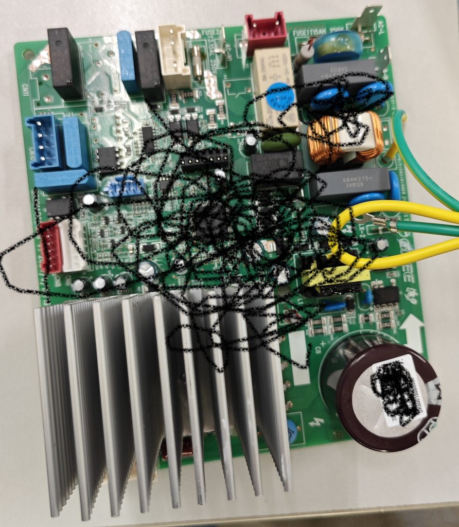
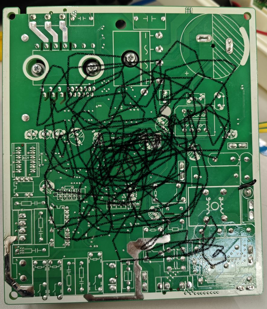
functional insulation as well as other insulation exists on circuit boards. Typically, the surface environment of a circuit board is determined to be either Pollution degree 3 or pollution degree 2.
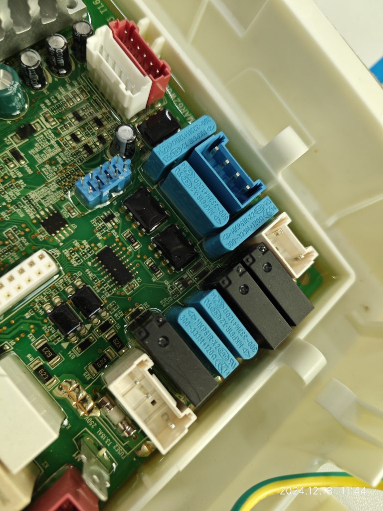
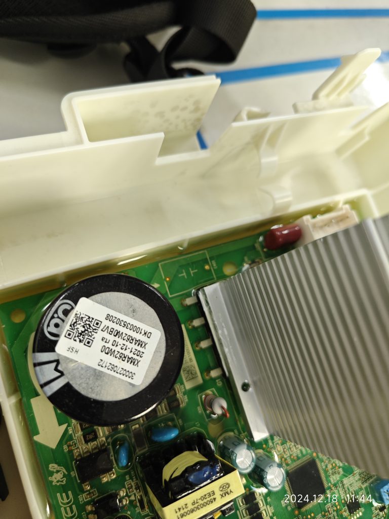
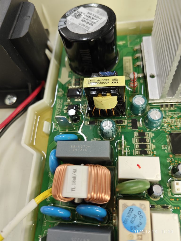
If the circuit board is mounted in an electrical box and sealed with a solid sealant, the sealing will look as follows:
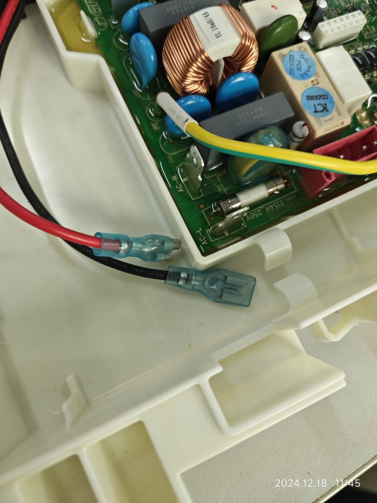
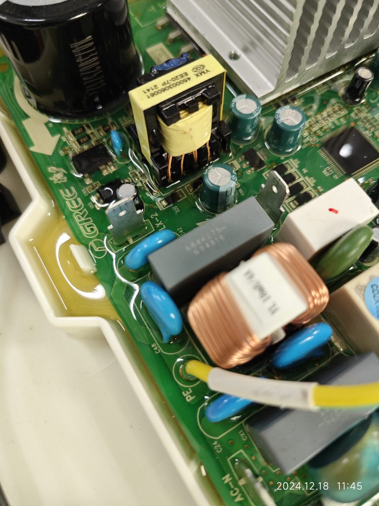
What should be the pollution degree of the functional insulation between the copper tracks on the PCB and between the energized parts on the component?
Here, the functional insulation is located inside the solid sealant and there is no contact between the path of the functional insulation and the outside air. According to the definition of electrical clearance, it can be assumed that there is no electrical clearance here. At the same time, the creepage distance is defined along the surface of the insulation, and obviously, there is no surface here either.
It may be argued that there is still a gap between the solid sealant and the PCB material, and that an clearance and creepage distance can be formed, but it is a pollution degree 1. This view is more conservative, because even if a gap is formed, it is not a continuous gap.
At the same time, the pictures show that this solid state sealant fills so well that it is essentially impossible to create a gap. The manufacturer also indicates that there is a vacuuming procedure prior to filling the solid state sealant. When we evaluate this type of structure, we can have some control over the material and specification of the solid state sealant, as well as some control over the filling process.
There may also be reinforced insulation internally, as there are isolation measures between the 220-240V circuit portion and the SELV circuit, which are judged by the same rules for clearance and creepage distances as functional insulation.

Similar Posts

  • Clause 3 – How to understand the definition of “self-resetting thermal cut-out”

    self-resetting thermal cut-out: thermal cut-out that automatically restores the current after the relevant part of the appliance has cooled down sufficiently In the definition there is a clear mention, when the temperature is cooled to a certain degree, in fact, its intention is to control the temperature is not too high, when the temperature is…

  • 第 3 項 – 「タイプ X アタッチメント」の定義の理解方法

    タイプXアタッチメント:電源コードの交換が容易な取付方法エントリへの注記 1: 電源コードは特別に用意され、製造元またはそのサービス代理店からのみ入手できる場合があります。特別に用意されたコードには器具の一部が含まれる場合があります。 まず、この定義は電源コード用です。次に、注記によると、コードは製造元またはそのサービス代理店からのみ入手できます。第三に、電源コードの交換が容易な構造であることが挙げられる。注記から、このコードが一般の家電付属品市場で購入できる場合、炊飯器の供給コードであることがわかります 上の図の例に示されているものは、実際にはここで言及されている電源コードに属しません。最後に、電源コードもアプライアンスの一部である場合があります。 Type X のアタッチメントは簡単に交換できる必要があります。以下の図に示すように、 電源コードは極性端子に接続されています。この接続方法は通常のマイナスドライバーで完了します。取り付けが容易なタイプですので、タイプXアタッチメントとして定義できます。同様の理由で、ここでの電源コードの接続が便利でクイックなコネクタを使用して接続されている場合は、タイプ X アタッチメントとして定義することもできますが、この構造はほとんど見られません。セクション 26.2 の最初の文を参照してください。「特別な準備ソフトウェアを備えた機器を除き、タイプ X の取り付け接続を備えた機器および固定配線に接続された機器には、ネジ、ナット、または同様の装置による接続用の端子が提供されなければなりません。接続はハンダ付けで行います。」これは、タイプ X の取り付け接続を完了するために、ネジ、ナット、または同様の接続デバイスを使用できることを意味します。逆に、ネジ、ナット、または同様の接続デバイスを使用して接続を完了する構造は、タイプ X アタッチメントとして定義できます。ここではろう付けについても言及されているので、ろう付けもタイプ X アタッチメントで使用される接続方法であると考える理由がありますが、個人的にはろう付けは簡単な接続方法ではないため、タイプ X アタッチメントとはみなせないと考えています。ろう付けを伴う場合は、ろう付けよりも簡単なはんだ付けを検討しますが、はんだ付けも容易ではないと思いますので、Type Xアタッチメント接続と判断することはお勧めできません。タイプXの付属品は現在では非常に珍しいと言わざるを得ません。技術の向上と材料の最適化により、電源コードの損傷はほとんど発生しなくなり、たとえ電源コードが損傷したとしても、一般のユーザーが自分で修理や交換することは困難です。ほとんどの電気製品はタイプ Y の取り付け構造を採用しています。標準でタイプ X の取り付けを定義したとき、後進技術により多くの電源コードが損傷したため、この安全規則が規定されました。 It has to be said that type X attachment is very rare now. Due to the improvement of technology and the optimization of materials, the damage of…

  • 第3項「定格インパルス電圧」の定義の見方

    定格インパルス電圧: 機器の定格電圧と過電圧カテゴリから導出される電圧。過渡過電圧に対する絶縁の指定された耐力を特徴づけます。 初心者にとって、この定義の物理的な意味を理解する必要はありません。規格におけるこの電圧値の主な用途は、クリアランスの制限値を決定することです。表 15 を参照すると、定格インパルス電圧値を直接決定できます。過電圧カテゴリ(OVC)は標準IEC 60664-1から来ていると言わざるを得ません。以下の表に定義を示します。 一方、過電圧カテゴリ(OVC)については説明図があります。 On the other hand, there is a drawing to explain overvoltage category(OVC).

  • 第 3 項 – 「クラス 0 アプライアンス」の定義の理解方法

    クラス 0 機器: 感電に対する保護が基礎絶縁のみに依存しており、導電性のアクセス可能な部品があったとしても、設備の固定配線内の保護導体に接続するための手段がなく、万一の場合に信頼できる機器。環境に設置された基礎断熱材の欠陥。注記 クラス 0 機器には、基礎絶縁の一部または全体を形成する絶縁材料のエンクロージャ、または適切な絶縁によって充電部から分離された金属エンクロージャのいずれかが備えられています。絶縁材の筐体を備えた機器に内部部品を接地するための設備がある場合、それはクラス I 機器またはクラス 0I 機器とみなされます。 この種の機器には保護接地装置がなく、同時に充電部を絶縁層で 1 層だけ包むか、絶縁層を使用して使用者を充電部から隔離します。ほとんどの国ではクラス 0 のアプライアンスを受け入れません。クラス 0 機器を受け入れられるのは、主電源電圧 (定格電圧) が日本などの 100 V と米国やメキシコなどの 120 V の一部の国だけです。ここで、同じ入力電力を達成するためには(たとえば、定格入力電力が 3000W のルームヒーター)、定格電圧が低いほど、対応する動作電流が大きくなることに言及する必要があります。逆に、定格電圧が高いと、それに対応する入力電流は小さくなります。大電流の場合、製品内の通電部品の発熱がより深刻になり、火災の可能性も高まるため、防火要件がより厳しくなります。低電流高電圧の場合、通電部の発熱はそれほど深刻ではありませんが、高電圧のため絶縁破壊の可能性が高くなり、感電防止の要件がより厳しくなります。 IEC 60335 シリーズの規格には、感電に対する保護に関して非常に高い要件が定められているのはこのためです。 IEC 60335 規格の主な作成者は、定格電圧 220 ~ 240V の国の専門家です。一方、米国の UL シリーズ規格には防火に関するさらに厳しい要件があります。通常、全ての充電部を基礎絶縁のみで保護するような機器は存在しません。感電に対する保護測定のほとんどは、二重絶縁または強化絶縁の要件を満たすことができるのが一般的です。もちろん基礎絶縁+接地保護構造もございます。一般的な状況は、電源コードのワイヤ シースが 1 層だけであり、デバイスの保護レベルは電源コードの基本絶縁、つまり最低の保護レベルのクラス 0 によって決まります。 次の 2 つの図は、クラス 0 アプライアンスの電源コードの情報を示しています。 1 つは回路図を示し、もう 1 つはプラグ付きの電源コードを示します。 次の図は、クラス…

  • Clause 3 – How to understand the definition of “built-in appliance”

    built-in appliance: fixed appliance intended to be installed in a cabinet, in a prepared recess in a wall or in a similar location. Here, because the appliance must be installed in a reserved position (usually a cubic space with only one side open), it is a fixed installation and can be regarded as a fixed…

  • Clause 3 – How to understand the definition of “portable appliance”

    portable appliance: appliance that is intended to be moved while in operation or an appliance, other than a fixed appliance, having a mass less than 18 kg. This item is relatively easy to understand. Products that are less than 18kg are relatively light, so they are easy to move during operation, including humidifiers, fans, air…