Clause 3 – How to understand the definition of “thermal cut-out”

thermal-cut-out: device which during abnormal operation limits the temperature of the controlled part by automatically opening the circuit, or by reducing the current, and is constructed so that its setting cannot be altered by the user.

There are three key provisions here. First, the thermal cut-out is a heat-sensing element, second, it can only be actuated during abnormal operation, and third, it cannot be adjusted by the user. Meanwhile the definition mentions that its function is to limit the temperature, and it does so by opening the circuit or reducing the current. Usually, we would think that its function is to prevent the temperature from being too high, indeed, most of its function is to prevent the temperature from being too high; however, in my opinion it can also be used to prevent the temperature from being too low, for example, in refrigerators or air-conditioning products. However, when we look at the definition of self-resetting thermal cut-out, the standard actually wants to limit just the high temperature state.
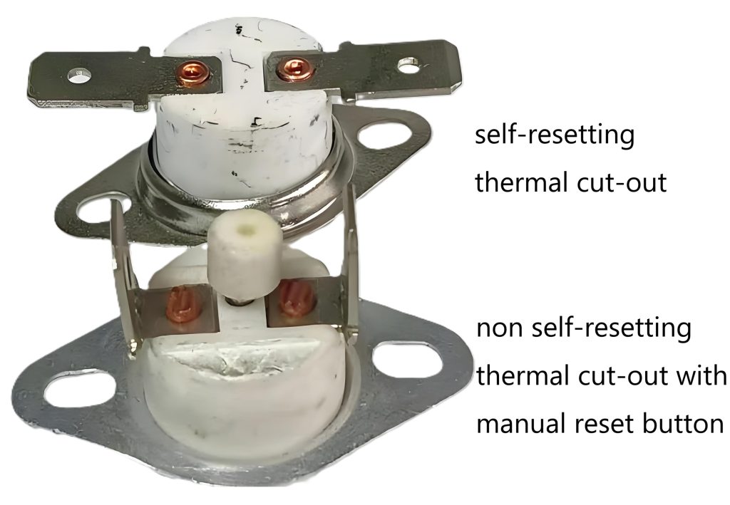
Thermal cut-out is a broad definition, which is subdivided into three categories of thermally sensitive protective devices, namely, self-resetting thermal cut-out, non-self-resetting thermal cut-out, and thermal link.
In normal operation, the component that operates may be a thermostat or temperature limiter, while in abnormal operation the component that operates is a thermal cut-out or a protective device.

Similar Posts

  • 第3項「二重絶縁」の定義の見方

    二重絶縁:基礎絶縁と補助絶縁を併用した絶縁方式 次の回路基板の画像にはアニメーション効果があります。点線の右側は動作電圧 220 ~ 240V のアクセス不可能な部分であり、点線の左側は最大動作電圧 24V のアクセス可能な部分です (点線の位置の構造が正常であると仮定します)。ラインは二重絶縁または強化絶縁の要件を満たしています)。効果的な絶縁を確保するために、一般的に、点線の右側のワイヤ (赤と青の内部ワイヤ) は、左側の比較的細い内部ワイヤに触れることはできません。右側のワイヤのワイヤ シースは基礎絶縁です。これは、ワイヤ シースが充電部と直接接触しており、充電部を保護する最初の層であるためです。左側の電線の電線シースは補助絶縁としてのみ定義できますが、第 29.3 項の補助絶縁の要件を満たしているかどうかは、第 29.3 項を導入する際に分析されます。 ここで、左側の電線の電線被覆を基礎絶縁、右側の電線の電線被覆を補助絶縁とすることはできないことに注意してください。 As shown in the following two pictures(fan), the internal lead wires sheath in the left picture is basic insulation, and the bottom plate of the outer casing is additional insulation. The following circuit board picture has an…

  • 第3項 「定格周波数」の定義の見方

    定格周波数: メーカーによってアプライアンスに割り当てられた周波数。 一般に、定格周波数は、製品設計時の対象市場国の標準実用周波数です。世界中で実用周波数は 50 Hz と 60 Hz の 2 つだけであるため、値は 50 Hz または 60 Hz、または 50 と 60 Hz の両方のみになります。 定格周波数、定格電流または定格電力入力、定格電圧などは、機器を特徴付ける基本パラメータであり、対象市場のニーズやユーティリティ条件から導き出されます。規格に従って試験を行う場合、これらのパラメータに従って試験条件を設定します。したがって、これらのパラメータはテスト前に確認する必要があります。確認しないと、作業の重複が生じ、誤ったテスト結果が生成されます。

  • 第3項 – 「定格電力入力範囲」の定義の見方

    定格電力入力範囲: メーカーによってアプライアンスに割り当てられた電力入力範囲。下限値と上限値で表されます。 この定義は定格電圧範囲に対応しています。つまり、定格電力入力には上限と下限の範囲がラベル付けされています。例:定格電圧範囲AC220~240V、定格入力電力範囲2000~2200Wの石英管ルームヒーター

  • 第 3 項 – 「クラス III 機器」の定義の理解方法

    クラスⅢ機器:感電に対する保護が安全特別低電圧の供給に依存しており、安全特別低電圧以上の電圧が発生しない機器注記 SELV での供給に加えて基礎絶縁が必要になる場合があります。 8.1.4を参照してください。 「安全特別低電圧」の4文字には「安全」という文字が入っておりますが、これはSELVが安全であるという意味ではなく、直接触れても安全であるとは限りません。規格 8.1.4 の要件を満たす安全特別低電圧回路のみに直接触れることができます。これについては、8.1.4 項を分析する際に具体的に分析して説明します。 下図に示すファンはクラス III アプライアンスとして定義できます。ただし、このファンには 2 つの耳があるため、第 22.44 条に準拠していません。詳細は後ほど説明させていただきます。 The fan shown in the figure below can be defined as a class III appliance. However, this fan has two ears, which makes it not compliant with clause 22.44. We will explain the details later.

  • 第 3 項 – 第 3.1.1 ~ 3.1.8 項の「定格」の定義の理解方法

    3.1.3項を除く3.1.1項から3.1.8項までの定格電圧、定格電圧範囲、定格電力入力、定格電力入力範囲、定格電流、定格周波数、定格周波数範囲の7項目が定格項目となります。 . 標準の意図を要約すると、“評価” は、メーカーによってアプライアンスに割り当てられた一連のパラメータを表します。 第 7 条の要件に従って、この格付けグループのパラメータの一部は通常、格付けラベルにマークする必要があります。製品設計者はユーザーのニーズに応じてこれらのパラメータを決定します。定格電圧、定格周波数は製品を使用する場所の商用電源の条件により決まり、また国によっても異なりますので、使用条件に合わせて製品を設計する必要があります。さまざまな国。こちらが参考になります ウェブページ、ほぼすべての国の電力供給状況の情報を確認できます。定格電流または定格入力はユーザーの要求に従って決定されます。たとえば、ユーザーが強力なルームヒーターを必要とする場合、設計者は購入者の要求に従って定格入力電力 3000W のルームヒーターを設計します。逆に、 、たとえば 500 W 以下など、非常に低電力のルーム ヒーター用に設計することもできます。 規格に従って試験を行う前に、定格パラメータ値を確認する必要があります。規格内の多くの試験は定格パラメータ値に基づいて試験条件を設定するため、定格パラメータ値が間違っていると、ほとんどの試験結果が失われてしまいます。間違いなく間違っているでしょう。