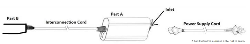
アプライアンスはコード セットによって供給され、パーツ A とパーツ B で構成されます。パーツ B は手持ち式で、相互接続コードによってパーツ A に接続されます。この情報は CTL 決定 OD-5002-F3:2021 に基づいています。
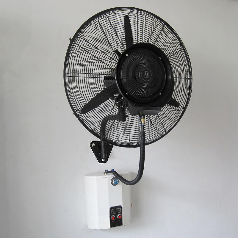
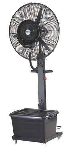
As shown in the figure below, a floor standing mist fan has a different structure from the wall mount mist fan shown in the figure above, but has the same function. The floor standing mist fan is an integral structure, but there is a cord outside connecting the fan head and the water tank below (the cord will pass through the middle support rod). For this kind of connection, the author believes that it is also an interconnection cords.
As shown in the figure below, this is a typical lead between the display circuit board and the main control circuit board of a split wall-mounted air conditioner indoor unit. Although the lead can be touched by manually opening the top cover, the lead is inside the appliance during normal use and is therefore not considered an interconnection cord. However, the lead still needs to meet the requirements of clause 22.8.
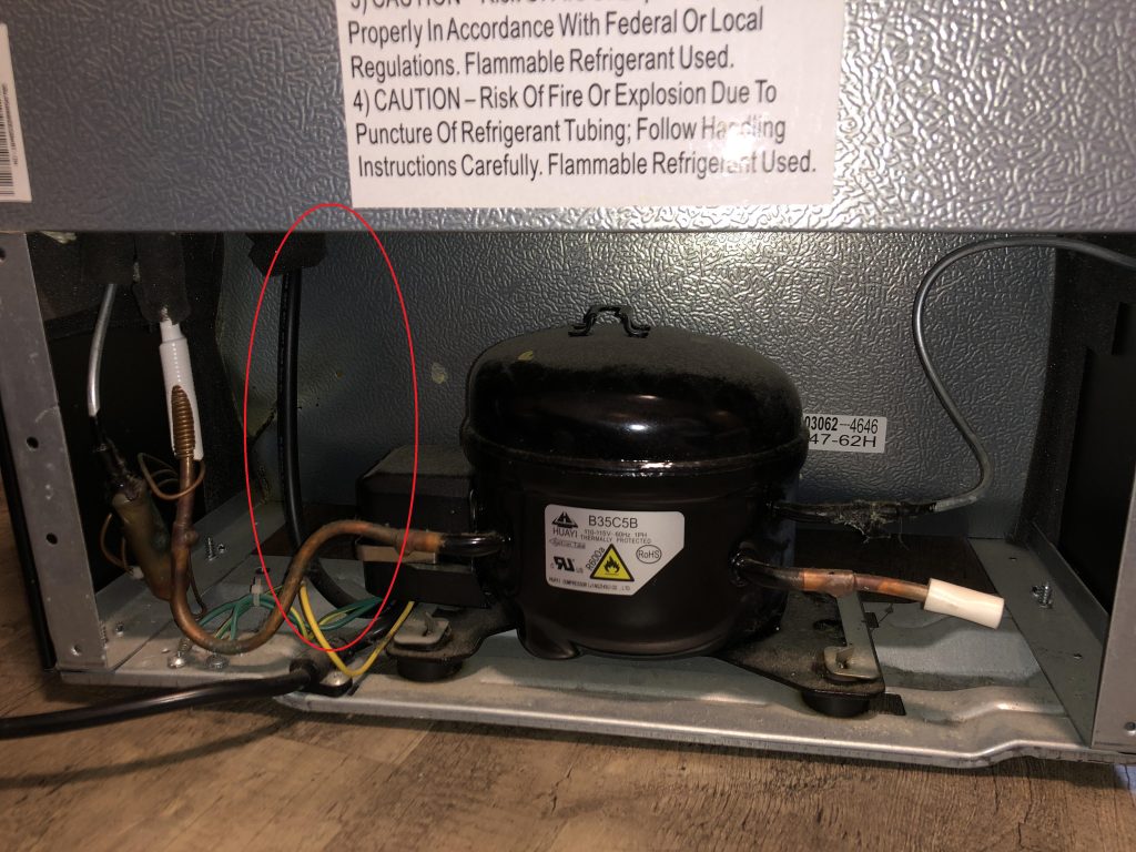
Here is a more controversial case, which is the cord inside the compressor compartment on the back of the refrigerator. The cord in the red circle in the figure below are considered to be interconnection cords by most third-party testing organizations or laboratories.
My personal opinion is that the cord in the refrigerator compressor compartment is not an interconnection cord. We can infer the intent of the standard from the requirements of 25.23 and 25.24. The standard requires that the interconnection cord needs to meet the requirements of the power cord. The power cord can be pulled, so the test of 25.15 is required. The power cord is characterized by being external to the appliance and can be touched and pulled. The refrigerator cord we are discussing here is unlikely to be touched and basically will not be pulled.
An appliance is supplied by a cord set and is composed of Part A and Part B, where Part B is handheld and connected to Part A by an interconnection cord. This information come from CTL decision OD-5002-F3:2021.
(IEC 60335-1 Ed. 5.1) battery-operated appliance: appliance deriving its energy from batteries enabling the appliance to perform its intended function without a mains connection.(IEC 60335-1 Ed. 6)battery-operated appliance: appliance deriving its energy from batteries enabling the appliance to perform its intended function without a supply connectionNote 1 to entry: A battery-operated appliance can have a…
all-pole disconnection: disconnection of both supply conductors by a single initiating action or, for multi-phase appliances, disconnection of all supply conductors by a single initiating actionNOTE For multi-phase appliances, the neutral conductor is not considered to be a supply conductor. Single-phase power: An AC power system composed of one live wire and one neutral wire.Three-phase…
self-resetting thermal cut-out: thermal cut-out that automatically restores the current after the relevant part of the appliance has cooled down sufficiently In the definition there is a clear mention, when the temperature is cooled to a certain degree, in fact, its intention is to control the temperature is not too high, when the temperature is…
functional insulation as well as other insulation exists on circuit boards. Typically, the surface environment of a circuit board is determined to be either Pollution degree 3 or pollution degree 2.If the circuit board is mounted in an electrical box and sealed with a solid sealant, the sealing will look as follows: What should be…
off position: stable position of a switching device in which the circuit controlled by the switch is disconnected from its supply or, for electronic disconnection, the circuit is de-energized.NOTE The off position does not imply an all-pole disconnection. With reference to the content in the NOTE, both all-pole disconnection and single-pole disconnection are a stable…
hand-held appliance: portable appliance intended to held in the hand during normal use. Hair dryers, electric irons, hand-held vacuum cleaners, etc. are typical examples of hand-held appliances.