Clause 3 – How to understand the definition of “motor-operated appliance”
motor-operated appliance: appliance incorporating motors but without any heating element
Note 1 to entry: Magnetically driven appliances are considered to be motor-operated appliances.
Household electrical appliances usually use heating elements or motors to complete their designed functions. The main functions are heating, such as heating food or air, and rotation or mechanical movement of products, such as blenders and fans. The realization of these two functions is basically completed by heating elements or motors. For appliances with only motors without heating element is motor-operated applaince. Common motors include AC asynchronous motors for air conditioners and fans, series motors used in blenders or hair dryers, shaded pole motors, synchronous motors, stepper motors, DC brushless motors, DC variable frequency motors, etc. It is necessary for us to briefly introduce the characteristics of various motors.
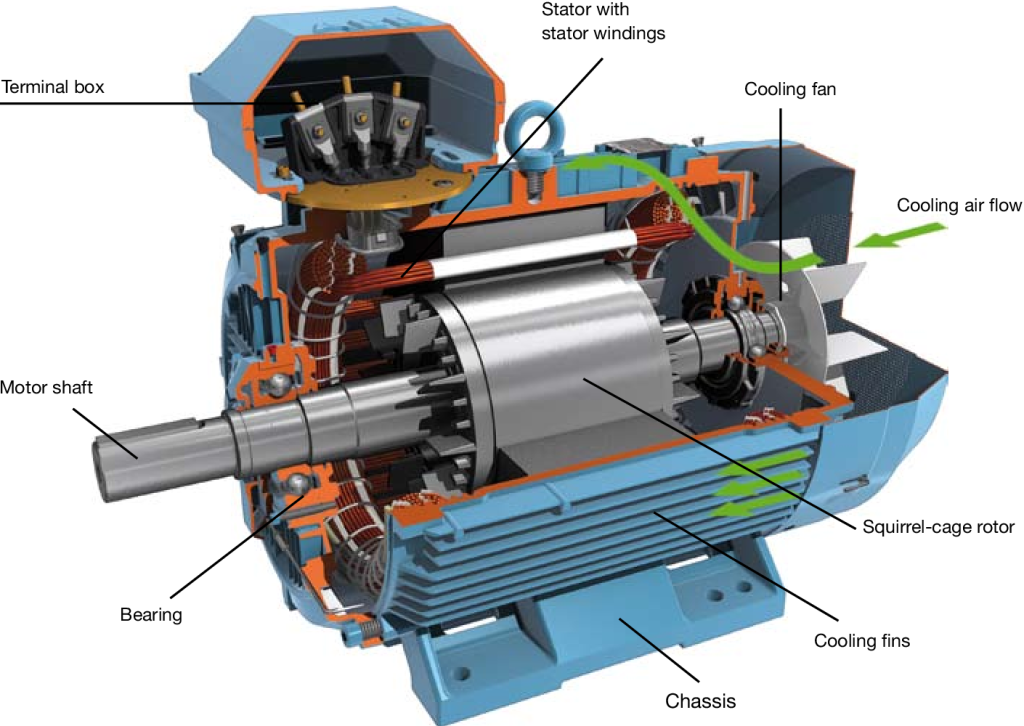
Shaded pole motor/squirrel cage motor:
The shaded pole motor/squirrel cage motor is the simplest type of unidirectional AC motor and usually uses a squirrel cage-type skewed slot cast aluminum rotor.
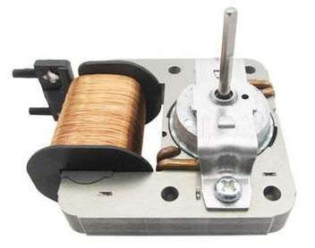
The shaded pole motor/squirrel cage motor has the following key characteristics:
- Simple Structure: The design is relatively straightforward, consisting mainly of a stator and rotor, with the rotor typically made of aluminum or copper bars short-circuited at both ends.
- High Efficiency: These motors have high efficiency, especially under rated load conditions, effectively converting electrical energy into mechanical energy.
- Low Maintenance: With no brushes or slip rings, squirrel cage motors require minimal maintenance, leading to stable operation and a long lifespan.
- Self-Starting Ability: Squirrel cage motors can start directly from the power supply, exhibiting good self-starting characteristics.
- High Starting Torque: They can provide significant starting torque, making them suitable for various industrial applications.
- Strong Load Adaptability: These motors can handle different load conditions well, particularly performing effectively under variable load situations.
- Cost-Effectiveness: Compared to other types of motors, squirrel cage motors have lower manufacturing costs and offer good economic value due to their high efficiency and low maintenance needs.
- Wide Applications: They are commonly used in pumps, fans, conveyors, compressors, and a variety of other industrial and commercial equipment.
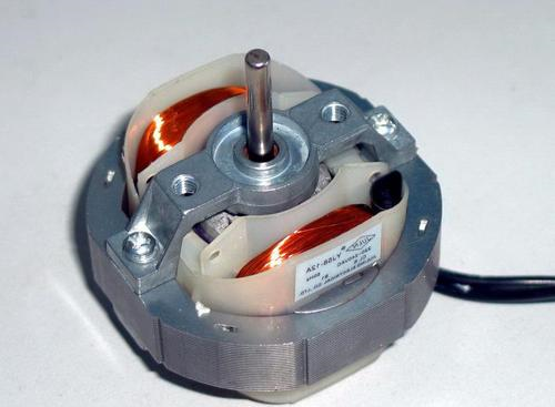
Single-phase asynchronous motors:
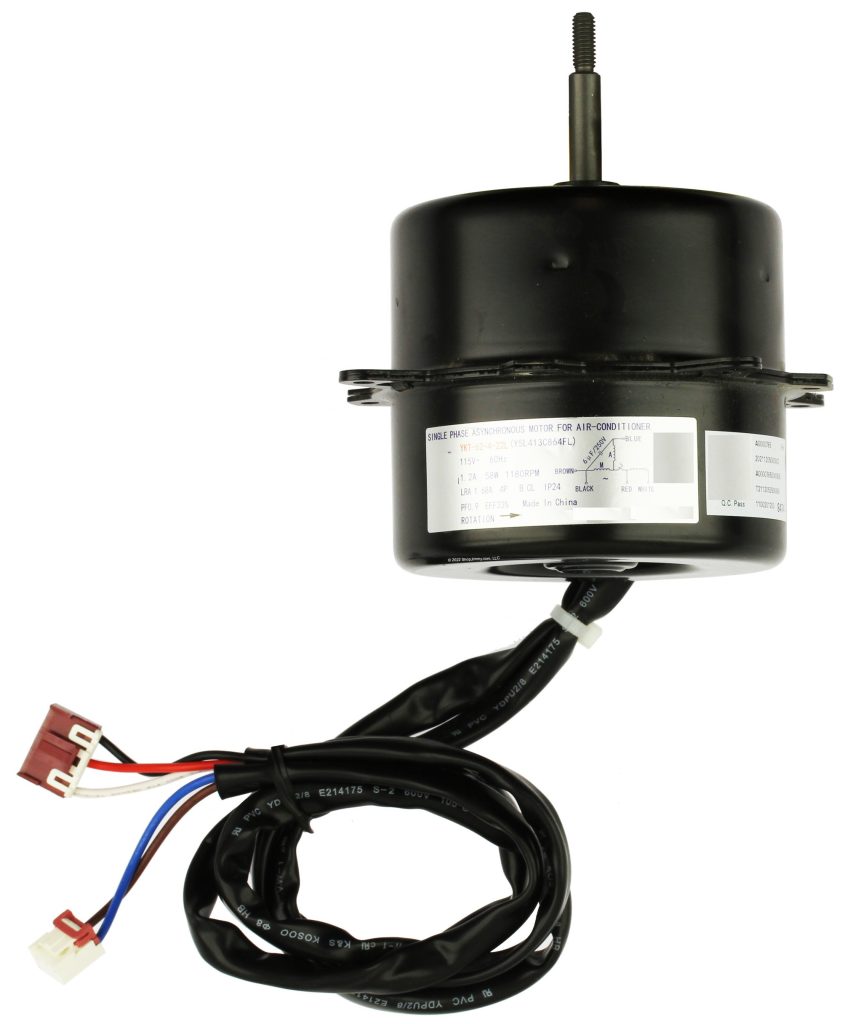
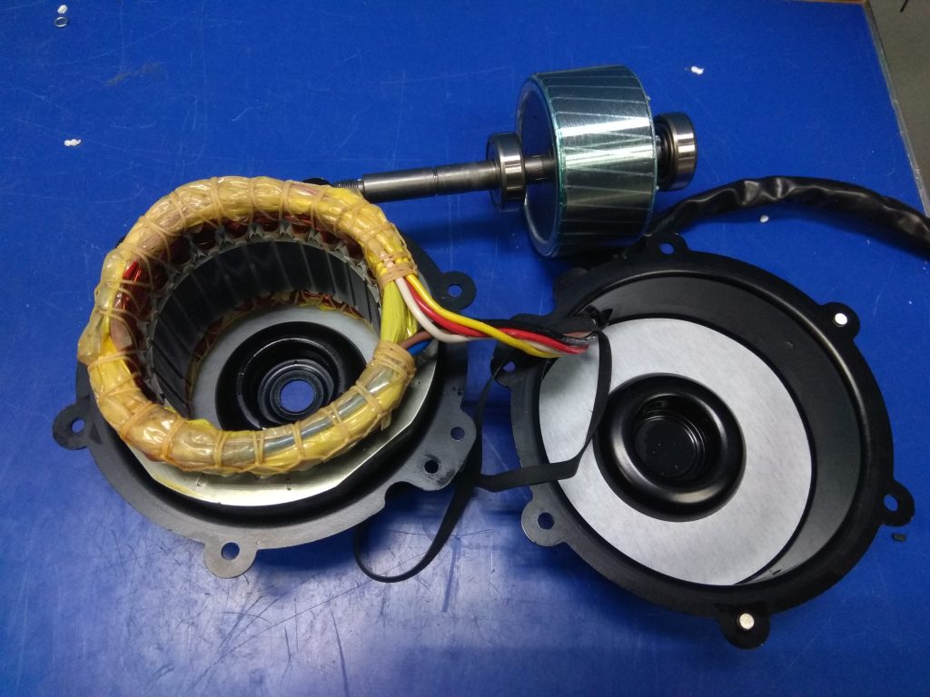
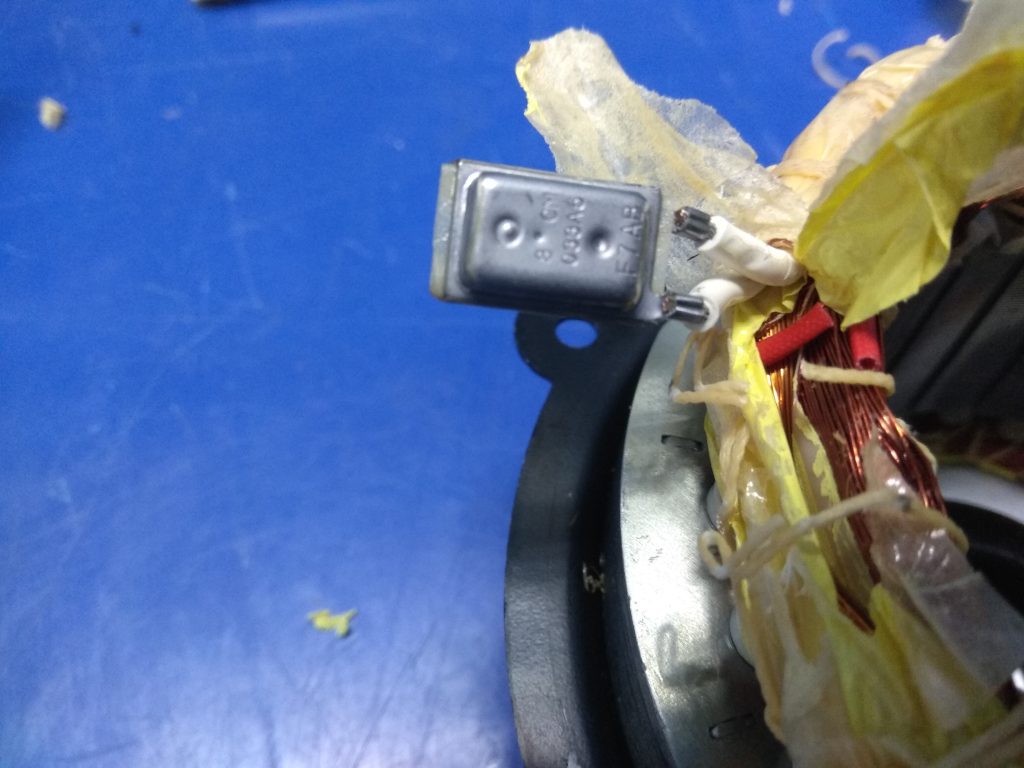
Single-phase asynchronous motors have the following characteristics:
- Simple Structure: These motors have a straightforward design, typically consisting of a stator, rotor, and auxiliary winding.
- Starting Method: Single-phase power cannot create a rotating magnetic field on its own, so these motors usually require additional starting windings or capacitors for startup, commonly using capacitor start or split-phase methods.
- Speed Characteristics: The speed is relatively stable, but compared to three-phase motors, the speed-load characteristics and efficiency are generally lower.
- Power Range: They typically operate at lower power levels, making them suitable for applications in household appliances and small machinery.
- Noise and Vibration: They may produce more noise and vibration during operation compared to three-phase motors.
- Starting Torque: The starting torque is usually lower, which can hinder direct startup under heavy load conditions.
- Cost-Effectiveness: Manufacturing and maintenance costs are typically lower, making them ideal for household appliances and small devices.
Application Range: Commonly used in small fans, air conditioners, refrigerators, and pumps in both home and small industrial settings.
Squirrel cage motors typically have higher efficiency compared to single-phase asynchronous motors. This is mainly due to their design, which allows for better performance under load and reduced losses. Squirrel cage motors operate more efficiently, especially at full load, while single-phase motors may experience lower efficiency, particularly at partial loads. Therefore, for applications requiring higher efficiency and consistent performance, squirrel cage motors are usually the preferred choice.
DC Reduction step gear stepper motor:
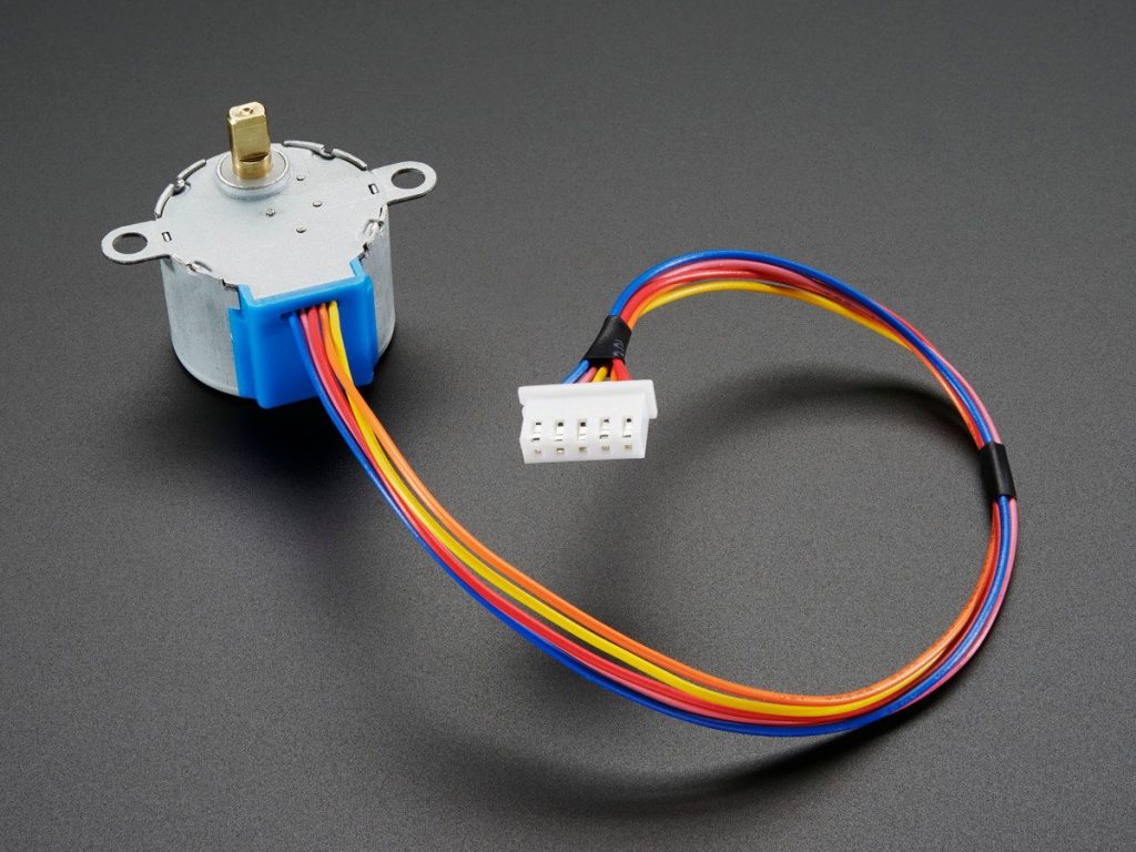
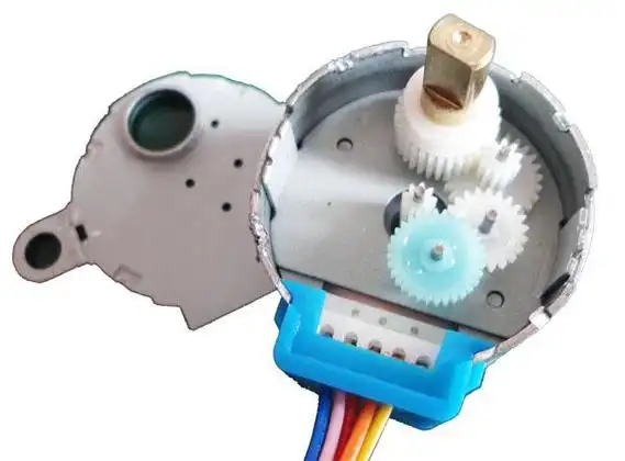
A DC reduction step gear stepper motor combines the characteristics of a stepper motor with a geared reduction system. This type of motor is valued for its precision control and increased torque, making it suitable for applications that require slow, controlled, and high-torque movement. Here are its key characteristics:
- Precise Positioning: With its stepwise rotation, a stepper motor can provide highly accurate positioning, as each step represents a specific increment of rotation. The addition of a reduction gear enhances this accuracy by allowing smaller steps in the output.
- Increased Torque: The reduction gear mechanism increases torque output by reducing the speed of the motor. This is beneficial for applications that require higher torque at lower speeds, such as robotics, CNC machines, and automation systems.
- Improved Holding Torque: The motor can maintain its position when not in motion (holding torque), which is ideal for applications that need to hold a load steady without additional power.
- Lower Speed, High Precision: Due to the reduction gear, the motor operates at a lower speed but with increased precision. This is useful in applications where controlled, slow movements are required.
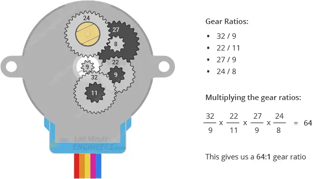
- Reduction Ratio: The gear reduction system is available in different ratios, allowing users to select the gear ratio that best meets their speed and torque requirements. Common ratios range from 4:1 to 100:1, affecting both torque and resolution.
- Steady and Reliable Operation: This type of motor is known for providing stable, repeatable movements. It is less prone to stalling or losing steps, thanks to the torque amplification provided by the reduction gear.
- Heat Generation: Geared stepper motors can generate heat during prolonged operation, especially at lower speeds and high loads. Proper ventilation or heat management may be required in demanding applications.
- Power Consumption: While stepper motors tend to consume more power than DC motors when holding a position, the gear reduction can reduce the load on the motor, potentially lowering overall power consumption.
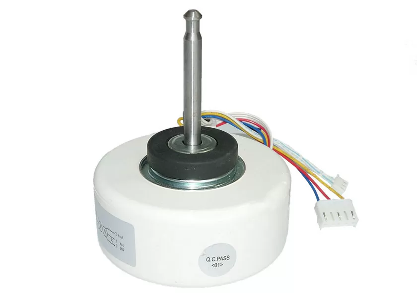
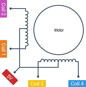
Small Synchronous Gear Motor:
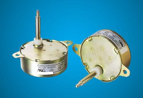
Small synchronous gear motors are compact devices that combine a synchronous motor with a gear reduction mechanism. Here are their key characteristics:
- Synchronous Operation: The rotor of a synchronous gear motor rotates at the same speed as the rotating magnetic field of the stator. This leads to precise speed control and consistent performance.
- Gear Reduction: The integrated gear system reduces the output speed while increasing torque. This is beneficial for applications requiring high torque at lower speeds, such as in robotics or automation.
- High Efficiency: Synchronous motors are generally more efficient than their induction counterparts, especially under load. This efficiency translates to lower energy consumption in applications.
- Compact Size: Small synchronous gear motors are designed to be space-efficient, making them suitable for applications with limited space, like small appliances, toys, and robotic systems.
- Low Noise: These motors typically operate quietly compared to other types of motors, making them ideal for noise-sensitive environments.
- Stable Operation: They provide stable and reliable operation with minimal vibration, contributing to precise movements.
- Variable Speed Control: With the right control system, synchronous gear motors can achieve variable speed operation, allowing for adaptability in different applications.
- High Holding Torque: When stopped, they maintain their position effectively, which is important for applications that require precise positioning.
- Limited Start-Up Torque: While they perform well under steady conditions, synchronous motors may have lower start-up torque compared to some other motor types. They might need help to start under load.
- Wide Range of Applications: Commonly used in robotics, conveyor systems, small appliances, and other applications where controlled motion and space efficiency are essential.
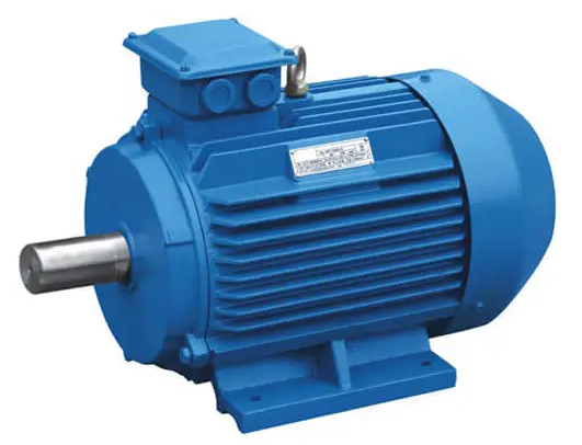
Series motor:
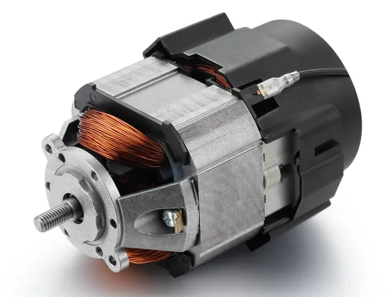
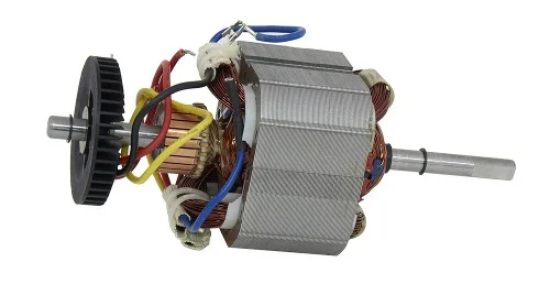
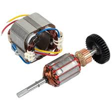
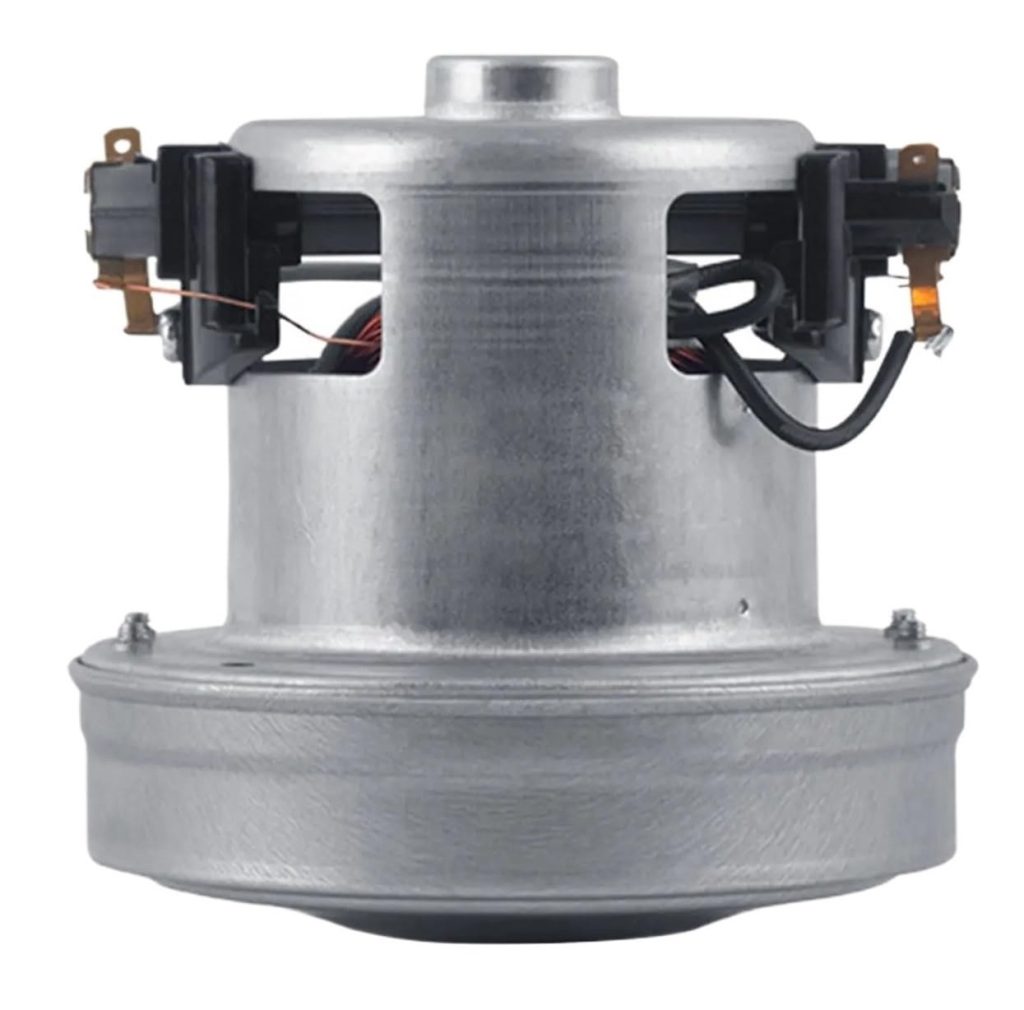
Series motors, a type of DC motor, have distinct characteristics that make them suitable for specific applications. Here are their key characteristics:
- High Starting Torque: Series motors produce high starting torque, making them ideal for applications requiring significant initial power, such as in electric vehicles, cranes, and hoists.
- Speed-Torque Relationship: The speed of a series motor decreases with an increase in load. As the load increases, the current increases, which in turn increases the magnetic field strength, leading to higher torque but lower speed.
- Simple Construction: Series motors have a relatively simple construction, with the armature winding and field winding connected in series. This design contributes to their ease of use and maintenance.
- Variable Speed: The speed of a series motor can vary significantly with load changes. While this can be advantageous in certain applications, it can also lead to instability at very low loads, potentially causing the motor to run away (over-speed).
- Not Suitable for Constant Speed Applications: Due to the significant variation in speed with changes in load, series motors are not ideal for applications where constant speed is crucial.
- High Current Draw: Series motors draw a high current at startup, which can necessitate the use of appropriate fuses or circuit breakers to prevent damage.
- Field Weakening: In some applications, it’s possible to weaken the field by reducing the current in the field winding, allowing for increased speed under light loads, although this can decrease efficiency.
- Good for Applications with Variable Load: Series motors are well-suited for applications where the load changes frequently, such as in trains, lifts, and electric vehicles.
- Limited Efficiency: Generally, series motors are less efficient than some other types of motors, especially under varying load conditions.
- Brush Wear: The wear on brushes can be significant in series motors due to the high current and the nature of operation, which may require more frequent maintenance.
Series motors are commonly used in blenders, hair dryers, vacuum cleaners, and other applications that require high starting torque.