Clause 3 – How to Understand the Definition of “off position”

off position: stable position of a switching device in which the circuit controlled by the switch is disconnected from its supply or, for electronic disconnection, the circuit is de-energized.
NOTE The off position does not imply an all-pole disconnection.

With reference to the content in the NOTE, both all-pole disconnection and single-pole disconnection are a stable condition of off position. So, what kind of electronic disconnection could be considered off position?
electronic disconnection, it could be achieved that the circuit is de-energized by relay, the circuit can also be disconnected by utilizing the switching function of a transistor, many other components capable of disconnecting circuits in a similar manner exist, though they will not be discussed here.

What we need to clarify is the difference between electronic disconnection and stand-by mode.

I checked standard IEC 335-1:1993 ED3.0, it gave us definitions below:
Off position: stable position of a switching device in which the circuit controlled by the switch is disconnected from its supply.
In the earlier version IEC 335-1:1976 ED2.0, the definition of “off position” was not yet established.

I searched the entire IEC 60335-1:2010+A1:2013+A2:2016 standard and found seven references to the “off position” within the document, like clause 7.10, clause 13.2, clause 16.2, clause 19.11, clause 19.13, clause 22.5, clause 22.55.
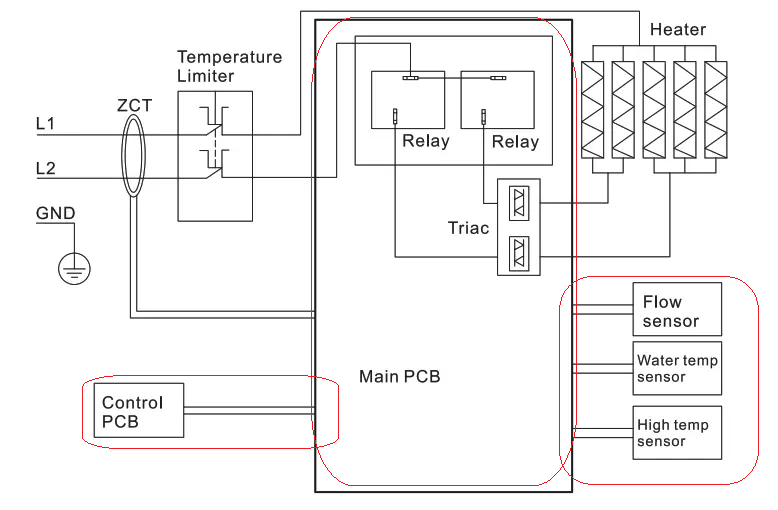
Particularly from the descriptions in clause 7.10 and clause 19.11, we can reasonably infer that electronic disconnection and stand-by mode should be considered as the off position. There is a word “circuit” in definition, it can be understood as the power supply circuit for the main energy-consuming components in the appliance, which excludes the electronic control circuits used for the PCB. As shown in the figure below, the content not highlighted by the red box corresponds to the “circuit” mentioned in the standard.

off position circuit diagram

Similar Posts

  • Clause 3 – How to understand the definition of “protective extra-low voltage circuit”

    protective extra-low voltage circuit: earthed circuit operating at safety extra-low voltage which is separated from other circuits by basic insulation and protective screening, double insulation or reinforced insulationNOTE 1 Protective screening is the separation of circuits from live parts by means of an earthed screen.NOTE 2 A protective extra-low voltage circuit is also known as…

  • Clause 3 – How to Understand the Definition of “all-pole disconnection”

    all-pole disconnection: disconnection of both supply conductors by a single initiating action or, for multi-phase appliances, disconnection of all supply conductors by a single initiating actionNOTE For multi-phase appliances, the neutral conductor is not considered to be a supply conductor. Single-phase power: An AC power system composed of one live wire and one neutral wire.​Three-phase…

  • 第3項「機能絶縁」の定義の見方

    機能的絶縁: 電位の異なる導電性部分間の絶縁であり、機器が適切に機能するためにのみ必要です。 下の図は典型的な機能絶縁の図です。PCB の銅レール層の図に示されているように、ラベルの茶色の部分は電源活線 (電流ヒューズ間に接続されている 2 つの茶色の位置)、青色の部分です。接続は電力線の中性線であり、活線であり、中性線には 2 つの線の間に電圧差があるため、選択した銅線レールの青色の部分と選択した銅線レールの茶色の部分の間の最短距離になります。レール、つまり機能絶縁体です。実際、通常の動作では、下の写真の回路基板、銅レール上の電圧は多くの場所で同じではないため、機能絶縁の形成により、読者は動作電圧によって独自の回路分析を行うことができます。各部分。 AC 非同期モーターの一般的な巻線接続図は次の図のようになります。図のコンデンサが動作しているとき、コンデンサの両端の電圧は通常、製品の定格電圧よりも高くなります。たとえば、定格電圧が 220V の場合、動作中にマルチメータで測定されるコンデンサの両端の電圧は通常 300V を超えます。このとき、コンデンサの両端間の機能絶縁を評価する場合、300V以上の使用電圧を基準に評価する必要がありますが、実際にはコンデンサ自体の機能絶縁は一般的には可能ではありません。コンデンサの端子がコンデンサのケース内に封入されているため測定されます。測定できる箇所はコンデンサの2本のリード線の端子台です。 下図に示すように、端子台には左側に活線が接続され、右側に中性線が接続されています。赤い線の位置は機能絶縁体の沿面距離です(クリアランスもここで決定できます)。 下の図に示されているキャリパーの測定値は、PCB 上のアダプターの入力のライブ銅線と中性銅線の間の機能絶縁を表しています。 As shown in the figure below, the terminal block has the live wire connected on the left and the neutral wire connected on the right. The position of the red line is the creepage distance of the…

  • 第 3 項 – 「クラス II アプライアンス」の定義の理解方法

    クラスⅡ機器:感電に対する保護を必要としない機器 基礎絶縁 ただし、追加の安全予防措置が提供される場合のみ 二重絶縁 または 強化絶縁、保護接地の規定や設置条件への依存はありません。 注 1 このようなアプライアンスは、次のタイプのいずれかになります。– 銘板、ネジ、リベットなどの絶縁された部品を除き、すべての金属部品を覆う、耐久性があり実質的に連続した断熱材の筐体を備えた機器 充電部 同等以上の絶縁により 強化絶縁;このような器具は断熱材入りと呼ばれます クラス II 機器;– 実質的に連続した金属製の筐体を備えた機器 二重絶縁 または 強化絶縁 は全体で使用されます。このような器具は金属ケースと呼ばれます クラス II 機器;– 断熱材で覆われた機器を組み合わせた器具 クラス II 機器 そして金属ケース クラス II 機器.注2 絶縁被覆の筐体 クラス II 機器 の一部または全体を形成する場合があります 補助絶縁 またはの 強化絶縁. ここでは二重の予防策の観点から考えていきます。基礎絶縁に加えて、製品には別の絶縁層も必要です。つまり、いずれかの層の絶縁が機能しなくなった場合でも、別の層の絶縁が保護の役割を果たすことを保証する二重絶縁対策です。強化絶縁による感電防止効果は二重絶縁と同等の場合が多く、二重の予防策としても有効と考えられます。規格によって定義されたクラス II 機器は、機器が独自のケーシング、絶縁電線、および絶縁電線のシースによって二重絶縁の効果を達成することを主に強調しています。接地対策が施された機器はクラス I 機器であるため、クラス II 機器には保護接地がありません。 クラス 0 機器を除き、大面積のプラスチックまたは絶縁ハウジングを備えたすべての機器は、通常、クラス II 機器として設計されています。ただし、金属ハウジングを備えたモーターもあり、その製品はクラス II 機器の要件を満たすことができますが、モーターには保護接地措置が講じられています。このアプライアンスはクラス I…

  • 第 3 項 – 「クラス 0I アプライアンス」の定義の理解方法

    クラス 0I 機器:全体に少なくとも基礎絶縁があり、接地端子が組み込まれているが、接地線のない電源コードと接地接点のないプラグを備えた機器 機器には外部保護導体(保護接地導体)を接続するための端子がありますが、固定配線には機器と保護導体を接続するための電線がなく、機器内部に接地導通を伝えるための配線や構造が設けられている場合があります。 日本では、以下のようなクラス0I機器専用のプラグがあります。 私の理解では、現在、クラス 0I 機器を使用しているのは日本だけです。通常、電源コードにはアース線が付いていますが、プラグ内のアースピンによってアースは行われません。代わりに、ツールを使用して別の端子または接地リングを接続し、効果的な接地を実現します。同様に、アプライアンスにもアース端子があります。設置前、この端子は外部配線に接続されておらず、通常は使用中および設置中に接続されます。