How are the creepage distances and electrical clearances of PTC heating element surfaces determined?

We are discussing here the second structure of the PTC heating element, PTC heating element structure please refer to the explanation of its definition.
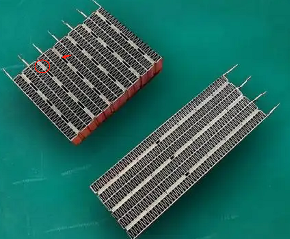
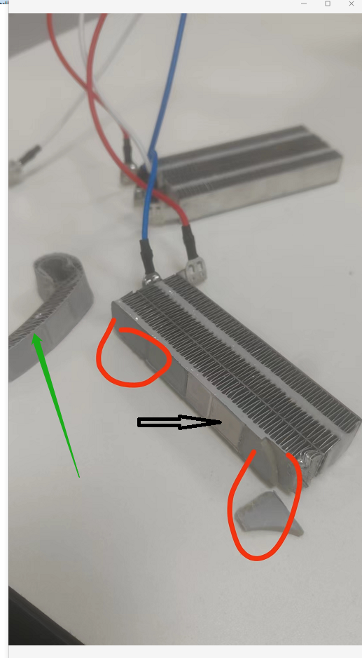
figure 1
figure 2

How is the creepage distance of the functional insulation at the location of the red circle in Figure 1 determined?
We all know that NOTE 1 of TABLE 18 section has the following requirements.
NOTE 1 For PTC heating elements, the creepage distances over the surface of the PTC material need not be greater than the associated clearance for working voltages less than 250 V and for pollution degrees 1 and 2. However, the creepage distances between terminations are those specified in the table.
In the first case, the heating units are fixed by means of a conductive adhesive and a heat sink, with some gaps between the heating units, but all the gaps are filled with an insulating adhesive.
As shown in Fig. 2, the heatsinks connected to the fire wire and the heatsinks connected to the zero wire are functionally insulated by means of an insulating structure filled with adhesive, whereby the electrical gaps and creepage distances are formed by the upper surface of the insulating adhesive. Since the environment in which the PTC heating elements are located is of pollution class III, then NOTE 1 of the TABLE 18 section does not apply. Therefore, the requirement for creepage distance is 3.2 mm if it is determined according to the 250 V operating voltage, but of course, we need to use the interpolation method to calculate the creepage distance limit at the rated voltage. Usually, the gap between the two heat sinks is about 2.4mm, then its resulting creepage distance and electrical clearance is generally 2.4mm, the smarter approach is to raise the gap on the insulating adhesive, made into a curved projection, which lengthens the creepage distance and electrical clearance.

The second case, the heating unit through the conductive glue and heat sinks are fixed, leaving a certain gap between the heating unit, but the surface of the heating unit are attached to the insulating adhesive.
And the requirements of the first case is the same, just the middle of the gap if you increase the creepage distance of the problem. In fact, it is not difficult to think of, can be in the middle of the gap near the location of the heating unit to increase the glue, glue can not be laid flat on the side of the heating unit, need to be laid into a U-shaped. Of course, this process is more difficult to realize, not recommended.

In the third case, the heating unit is only fixed by the conductive glue and the heat sink for sticking, and there is a gap between multiple heating units. See Figure 1, the upper left corner of the component. There is no insulating glue attached between the heat generating units or on the surface.
The electrical gap is present in the gaps. What is in dispute here is how to determine the creepage distance. According to conventional logic, there is no creepage distance. According to the definition of creepage distance, creepage distance is in the surface of the insulating material trip, two heat sinks between the heating unit is not an insulating material, so its surface can not form a creepage distance path. Since no creepage distance can be formed, the prerequisite of clause 29.2.4 is not satisfied, and therefore there is no need to assess the creepage distance of functional insulation.

However, I personally still believe that we need to consider creepage distances, because the existence of creepage distances also takes into account the deposition of contaminants on the surface of a material, which can lead to short circuits. Here the PTC heating element generally work in Pollution degree 3, the surface must be for the accumulation of a lot of pollutants, pollutants, if too much, will lead to functional insulation short-circuit, resulting in appliances or power supply lines in the protective device action. This is in fact a less safe means, and the standard does not allow for the operation of protective devices in the supply line.

Similar Posts

  • ข้อ 3 – วิธีทำความเข้าใจคำจำกัดความของ “ฉนวนพื้นฐาน”

    ตามที่แสดงในภาพซ้ายด้านล่าง เป็นภาพถ่ายฝาครอบด้านล่างของพัดลม และภาพขวาเป็นภาพถ่ายที่ไม่มีฝาครอบด้านล่าง ผิวลวดสีน้ำเงินและสีน้ำตาลภายในสายไฟในภาพด้านขวาถือได้ว่าเป็นฉนวนพื้นฐาน ในเวลาเดียวกัน สกินลวดสีขาว สีแดง และสีดำบนสวิตช์ที่เชื่อมต่อกับเปลือกสีดำสามารถถือเป็นฉนวนพื้นฐานได้ ส่วนที่มีกระแสไฟฟ้าที่นี่คือแกนทองแดงในเส้นลวด นอกจากนี้ ระยะห่างระหว่างตัวนำโลหะในสวิตช์และพื้นผิวด้านในของเปลือกสีขาวสามารถตัดสินได้ว่าเป็นฉนวนพื้นฐาน จากมุมมองของระยะตามผิวฉนวน กระแสไฟฟ้าในตัวนำภายในสวิตช์จะดำเนินการ (ไต่ขึ้น) ไปตามพื้นผิวฉนวนของสวิตช์ไปยังพื้นผิวด้านในของเปลือกสีขาว (มุมเล็กซ้ายของภาพขวา) และระยะนี้สามารถ ถือเป็นระยะห่างตามผิวฉนวนของฉนวนพื้นฐาน จากมุมมองของระยะห่างทางไฟฟ้า กระแสไฟฟ้าในตัวนำภายในสวิตช์จะถูกส่งโดยตรงผ่านอากาศระหว่างพื้นผิวด้านในของฝาครอบด้านล่างของพัดลมและเปลือกสวิตช์ และระยะห่างระหว่างอากาศนี้ถือเป็นระยะห่างของฉนวนพื้นฐาน (เปลือกพลาสติกสีขาวถือเป็นฉนวนเพิ่มเติม) ดังแสดงในรูปด้านล่าง ตัวนำเคลือบแล็คเกอร์ของขดลวดของมอเตอร์ได้รับการแก้ไขโดยกระดาษช่องสีขาวที่สอดเข้าไปในสเตเตอร์ของมอเตอร์ ขดลวดถูกระบุว่าเป็นชิ้นส่วนที่มีไฟฟ้าแบบเปิดโล่งตามมาตรฐาน ตัวนำเคลือบแล็คเกอร์ของขดลวดและสเตเตอร์ของมอเตอร์จะสร้างวงวนนำไฟฟ้าผ่านกระดาษช่อง (โดยทั่วไป หากเป็นเครื่องใช้ไฟฟ้าประเภท 1 สเตเตอร์ที่เชื่อมต่อกับตัวเรือนมอเตอร์จะถูกต่อสายดินด้วยเนื่องจากตัวเรือนมอเตอร์ต่อสายดิน ถ้าเป็นเช่นนั้น อุปกรณ์ประเภท II ตัวเรือนมอเตอร์ และสเตเตอร์ของมอเตอร์เป็นส่วนประกอบโลหะขั้นกลางที่ไม่มีการต่อสายดิน) แม้ว่าค่าการนำไฟฟ้าของกระดาษสล็อตจะไม่เพียงพอ แต่กระแสไฟอ่อนจะยังคงเกิดขึ้นบนกระดาษสล็อต ปริมาณกระแสไฟฟ้าที่สร้างขึ้นที่นี่เกี่ยวข้องโดยตรงกับประสิทธิภาพของกระดาษสล็อต วัสดุกระดาษช่องนี้สามารถกำหนดได้ว่าเป็นฉนวนพื้นฐาน พื้นผิวของกระดาษช่องสามารถเชื่อมต่อกับการเคลือบโลหะของขดลวด ดังนั้นระยะทางบนพื้นผิวกระดาษของช่องสามารถกำหนดเป็นระยะทางตามผิวฉนวนของฉนวนพื้นฐาน วัสดุของกระดาษสล็อตนั้นมีบทบาทเป็นฉนวนแข็ง (แม้ว่าจะไม่มีข้อกำหนดความหนาสำหรับฉนวนแข็ง แต่ก็ยังต้องเป็นไปตามข้อกำหนดกระแสไฟรั่วและความแข็งแรงทางไฟฟ้าของบทที่ 13 และ 16) ดังนั้น ระยะห่างทางไฟฟ้าในรูปด้านบนคือระยะห่างที่สั้นที่สุดระหว่างขดลวดและการเคลือบสเตเตอร์ในอากาศ ดังแสดงในรูปด้านล่าง และ nbsp; ลวดพันของมอเตอร์ไม่ได้รับการแก้ไขอย่างถูกต้องและอยู่ใกล้กับสเตเตอร์ของมอเตอร์มาก มันไม่สามารถตอบสนองข้อกำหนดระยะตามผิวฉนวนและระยะกวาดล้างของข้อ 29…

  • Clause 3 – How to understand the definition of “heating appliance”

    heating appliance: appliance incorporating heating elements but without any motor. Before introducing this definition, we need to briefly introduce the electric heating elements commonly used in household electrical appliances. PTC heating element: PTC (Positive Temperature Coefficient) heating elements are widely used for various heating applications because of their self-regulating properties and safety features. Here are…

  • ข้อ 3 – วิธีทำความเข้าใจคำจำกัดความของ “ไฟล์แนบประเภท Y”

    โดยทั่วไปแล้ว อุปกรณ์เสริมประเภท Y ใช้สำหรับสายไฟที่เปลี่ยนได้ยาก หรือเมื่อสัมผัสชิ้นส่วนที่เป็นอันตรายระหว่างการเปลี่ยน ดังนั้นจึงจำเป็นต้องเปลี่ยนสายไฟโดยผู้ผลิต หน่วยงานบริการ หรือบุคลากรที่มีคุณสมบัติคล้ายคลึงกัน ปัจจุบันเครื่องใช้ไฟฟ้าในครัวเรือนส่วนใหญ่ใช้โครงสร้างนี้ ตามที่แสดงในภาพสองภาพต่อไปนี้ หลังจากที่ถอดฝาครอบที่ด้านล่างของเครื่องออกแล้ว คุณจะมองเห็นที่รัดสายไฟและขั้วต่อสายไฟภายใน การถอดฝาครอบด้านล่างออกทำได้ค่อนข้างง่าย แต่หากสายไฟเชื่อมต่อด้วยขั้วต่อหัวนมที่คล้ายกันหรือยึดด้วยกลไก จะต้องใช้เครื่องมือระดับมืออาชีพหรือทำลายเพื่อเชื่อมต่อสายไฟใหม่ ซึ่งทำให้เปลี่ยนสายไฟได้ยาก มีความสมเหตุสมผลมากกว่าที่จะกำหนดโครงสร้างนี้เป็นไฟล์แนบประเภท Y As shown in the following two pictures, after removing the cover at the bottom of the appliance, you can see the cord clamp and the internal supply cord connector. Removing the bottom cover is relatively easy, but…

  • ข้อ 3 – วิธีทำความเข้าใจคำจำกัดความของ “ช่วงความถี่ที่กำหนด”

    ความถี่ที่กำหนดในรูปแบบของช่วง โดยทั่วไปคือ 50-60 Hz แต่ทุกประเทศในโลกมีความถี่หลัก 50 Hz หรือ 60 Hz จึงไม่มีค่าความถี่กลาง ดังนั้น คำจำกัดความจึงไม่มีความหมายมากนัก อย่างไรก็ตาม ยังมีผู้ซื้อหรือผู้ผลิตที่ให้ช่วงความถี่ในรูปแบบ 50-60Hz ในความคิดของฉัน แม้จะพิจารณาความผันผวนของความถี่ที่เกิดจากแรงดันไฟฟ้าของอาคารที่ไม่เสถียร 50-60Hz ก็ไม่ได้คำนึงถึงสถานการณ์ที่น้อยกว่า 50Hz หรือมากกว่า 60Hz ดังนั้น ฉันขอแนะนำให้ทำเครื่องหมายความถี่ที่กำหนดเป็น 50/60Hz โดยตรงTherefore, I recommend marking the rated frequency as 50/60Hz directly.

  • |

    If the PCB is sealed with solid sealant, how to determine the creepage distance and clearance?

    functional insulation as well as other insulation exists on circuit boards. Typically, the surface environment of a circuit board is determined to be either Pollution degree 3 or pollution degree 2.If the circuit board is mounted in an electrical box and sealed with a solid sealant, the sealing will look as follows: What should be…

  • ข้อ 3 – จะเข้าใจคำจำกัดความของ “ระยะห่างที่คืบคลาน” ได้อย่างไร

    คำจำกัดความของระยะห่างตามผิวฉนวนมาจากมาตรฐาน IEC 60664-1:2020 เนื่องจากเราต้องอธิบายระยะตามผิวฉนวน เราจึงต้องแสดงรูปภาพรูปที่ 4 ถึงรูปที่ 14 ในมาตรฐาน IEC 60664-1:2020 ในที่นี้ ผู้อ่านจะต้องพิจารณาอย่างรอบคอบถึงวิธีการกำหนด “X mm” หากมีร่องบนเส้นทางที่ทำให้เกิดระยะตามผิวฉนวน ก็จะมีสถานการณ์ร่องสะพาน โดยส่วนตัวผมคิดว่าสาเหตุหลักในการเชื่อมโยงคือการสะสมของสารมลพิษในร่อง มลพิษเหล่านี้ส่วนใหญ่เป็นฝุ่น และฝุ่นชื้นจะนำไฟฟ้าได้มากกว่า ดังนั้นการคัดลอกข้อความต้นฉบับของมาตรฐานจึงมีสมมติฐาน 3 ข้อดังต่อไปนี้: – ในกรณีที่ระยะห่างข้ามร่องน้อยกว่าความกว้าง X ที่ระบุ (ดูตารางที่ 1) ระยะห่างตามผิวฉนวนจะถูกวัดโดยตรงผ่านร่องและไม่คำนึงถึงรูปร่างของร่อง (ดูรูปที่ 4) – โดยที่ระยะห่างข้ามร่องเท่ากับหรือมากกว่าความกว้าง X ที่ระบุ (ดูตารางที่ 1) ระยะตามผิวฉนวนจะถูกวัดตามแนวโครงร่างของร่อง (ดูรูปที่ 5)– ช่องใดๆ ให้ถือว่าต่อเชื่อมด้วยตัวต่อฉนวนที่มีความยาวเท่ากับความกว้าง X ที่ระบุ และวางไว้ในตำแหน่งที่ให้ผลเสียมากที่สุด (ดูรูปที่ 6)– ระยะห่างจากอากาศและระยะห่างตามผิวฉนวนที่วัดระหว่างชิ้นส่วนซึ่งสามารถรับตำแหน่งที่แตกต่างกันโดยสัมพันธ์กัน ให้วัดเมื่อชิ้นส่วนเหล่านี้อยู่ในตำแหน่งที่ไม่เอื้ออำนวยที่สุดรูปที่ 4 – ข้ามร่องเงื่อนไข: เส้นทางที่พิจารณาประกอบด้วยร่องด้านขนานหรือบรรจบกันทุกความลึกที่มีความกว้างน้อยกว่า X…