8.1.5 What exactly does it protect against?

8.1.5 Live parts of built-in appliances, fixed appliances, and appliances delivered in separate units shall be protected by at least basic insulation before installation or assembly. Compliance is checked by inspection and the test in 8.1.1.
Why is this requirement in place? I believe there are three types of hazards that require protection.

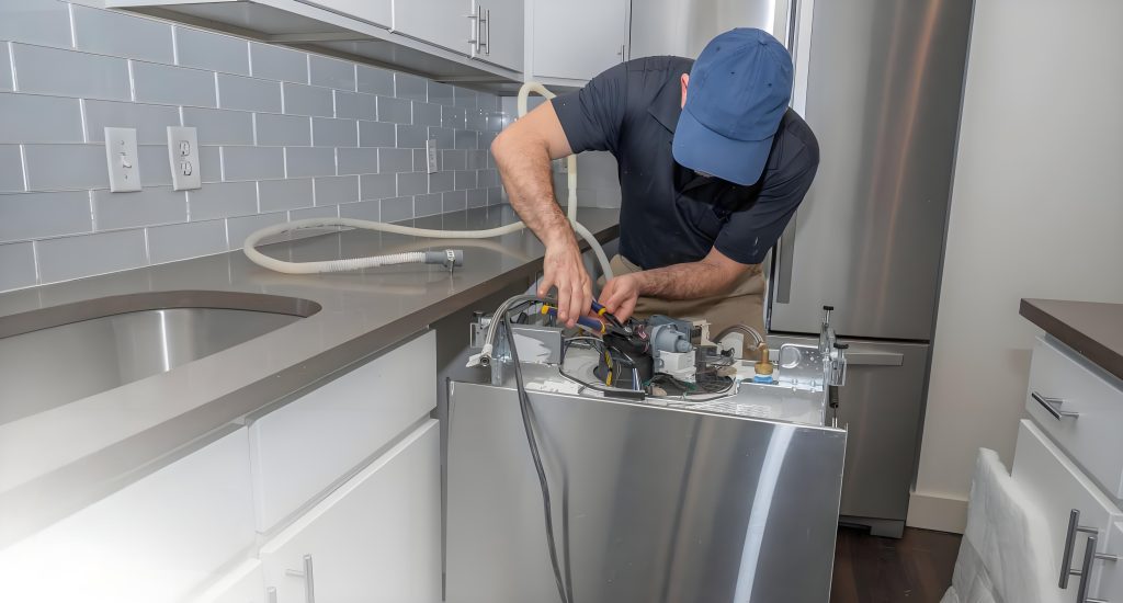
The first is an example of a built-in appliance, such as a dishwashing machine or a tableware sterilizer. Generally, after a dishwasher is installed in accordance with the instructions, except for the front surface, which is accessible, the other five surfaces are inaccessible. They are covered or enclosed by the space provided by the installation location, effectively preventing the risk of electric shock. However, during installation, installers typically don’t power on and test the appliance until it’s fully installed. For built-in products, installers typically power on the appliance to test its operation before placing it in its fixed location. In this case, the appliance isn’t protected from its surroundings, specifically the space where it’s installed. Imagine a scenario where, after unpacking the appliance at the user’s home, some terminals or wires are exposed. This creates a risk of accidental electric shock during installation. Therefore, the standard requires basic insulation protection before installation. To ensure effective basic insulation, we need to apply the test requirements in clause 8.1.1. Implementing the test requirements in clause 8.1.1 inevitably involves clause 22.11 and its definition of removable parts.
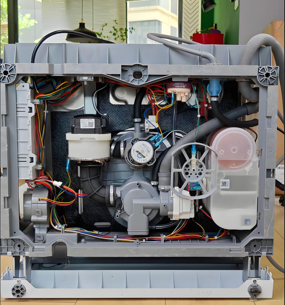
internal wire of dishwasher
Dishwasher Installation
push the dishwasher into cabinet

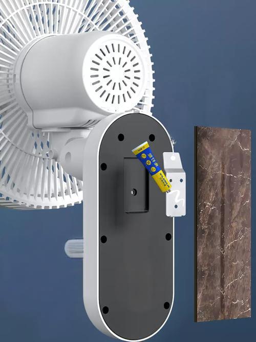
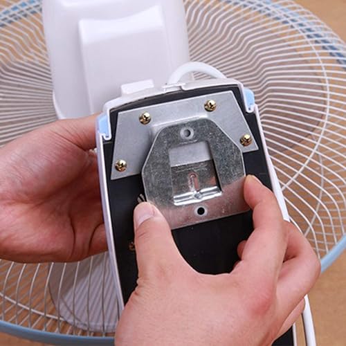
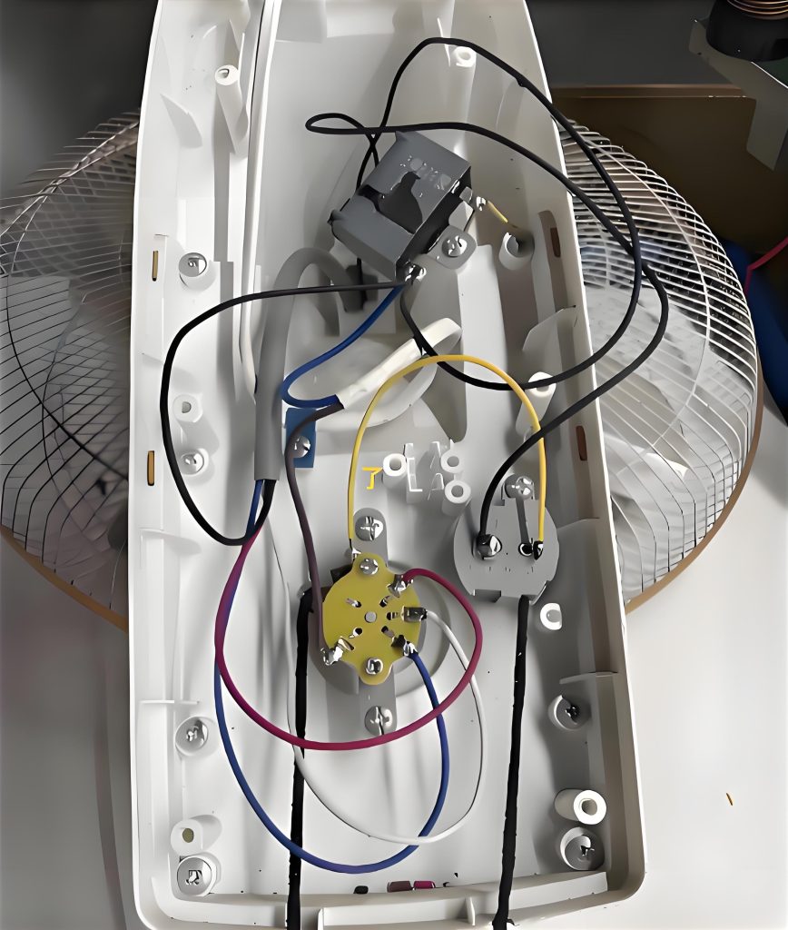
The second type, similar to the first, applies to fixed appliances, such as wall-mounted fans. These products are typically installed on-site and require the installation of a mounting plate or bracket. However, experienced installers will typically verify that the product is functioning properly before proceeding. During the power-on test run, the mounting surface is often not secured to the wall, rendering the wall ineffective. If the mounting surface has a large opening, allowing a finger to penetrate and contact live components, there is a risk of electric shock.
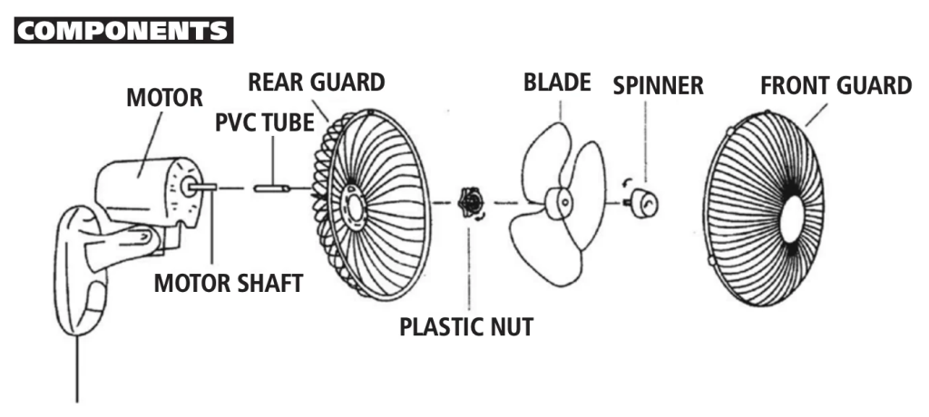
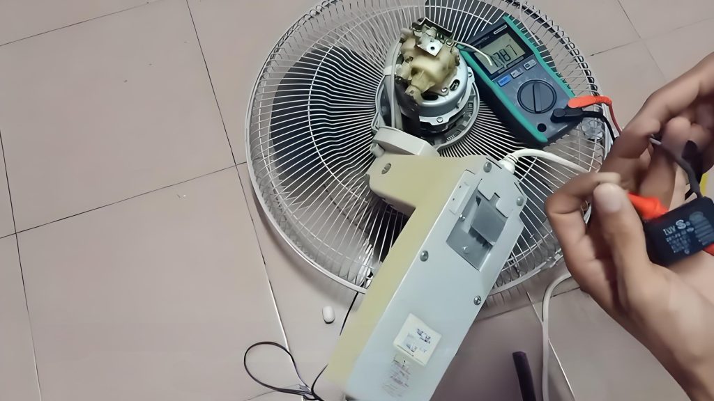
wall mounting fan exploded view
base pan of wall mount fan
wall mount fan base pan
wall mounting fan fixed support
internal view of base pan of wall mount fan

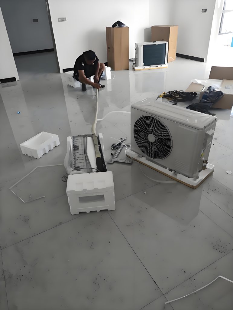
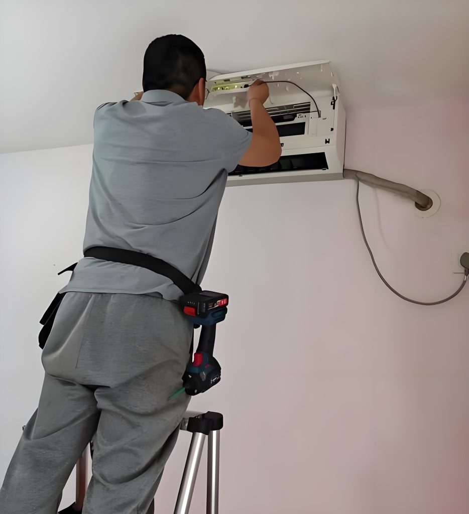
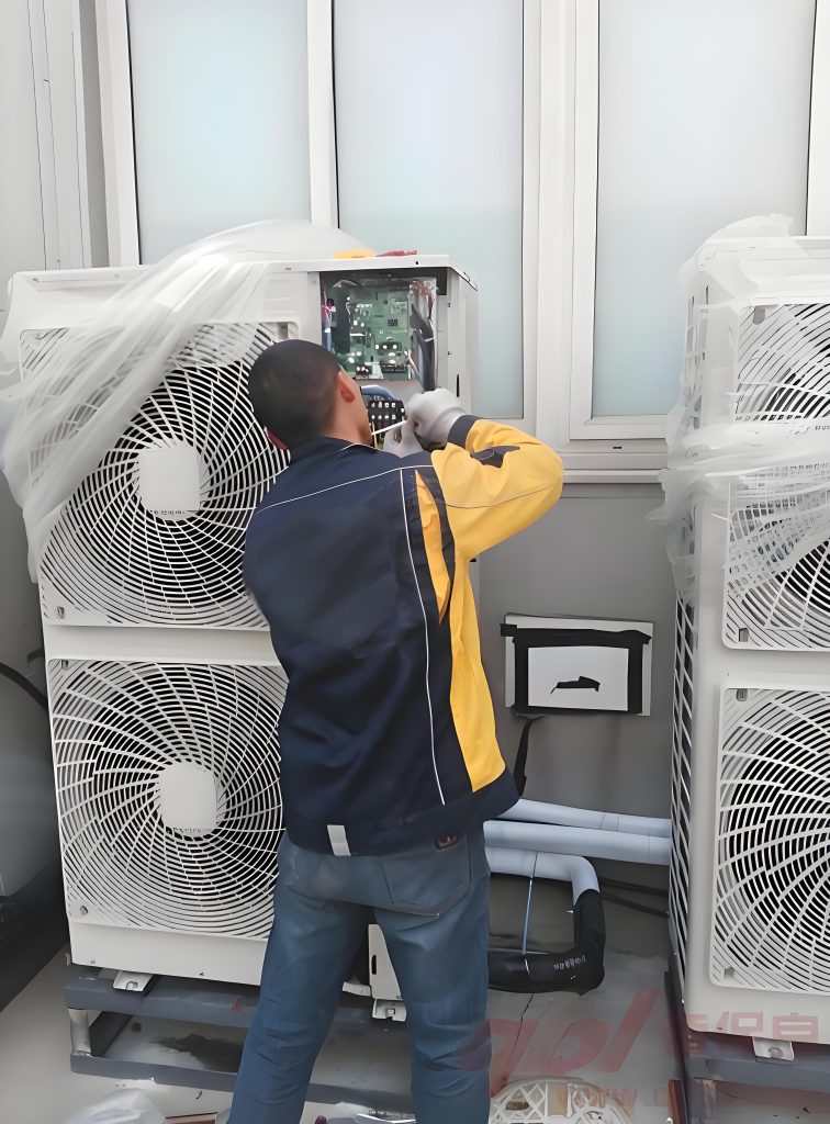
The third type is controversial. Split-type household air conditioners are typically delivered as separate, independent units. These products typically require on-site installation. During installation, is it possible that the outdoor unit has already been installed and connected to the mains power supply? The indoor unit installer is not the same person as the outdoor unit installer and is unaware of the outdoor unit’s installation progress. He or she needs to complete the wiring for both units, potentially completing the wiring while the outdoor unit is energized. A typical wiring task involves connecting the indoor and outdoor unit interconnecting cables. As described in the second scenario, both indoor and outdoor unit wiring terminals require basic insulation protection. However, does the separately delivered interconnecting cable also require basic insulation protection? Note that the interconnecting cables used here all comply with clause 25.23. They all have insulating sheaths, but may have exposed conductors at their ends. The basic insulation protection we will discuss below applies to these exposed conductors. If the standard is strictly adhered to, I believe requiring basic insulation is acceptable. However, in actual production and manufacturing, it is difficult to achieve, and even if it is, the cost is considerable. Therefore, I personally believe that separately delivered interconnecting cables do not require additional basic insulation protection.
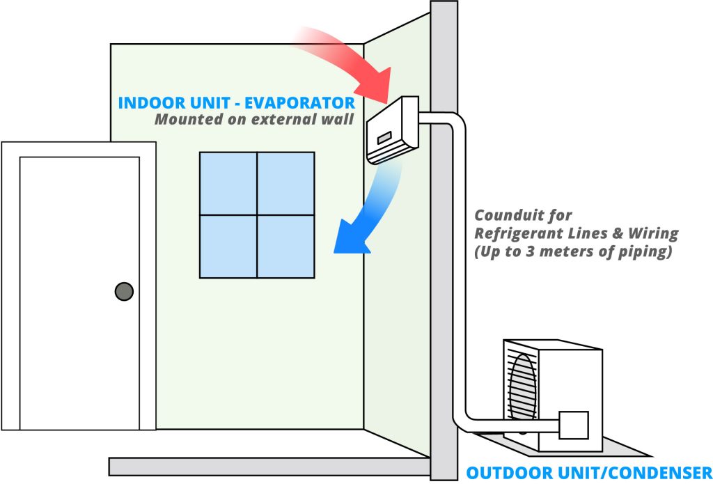
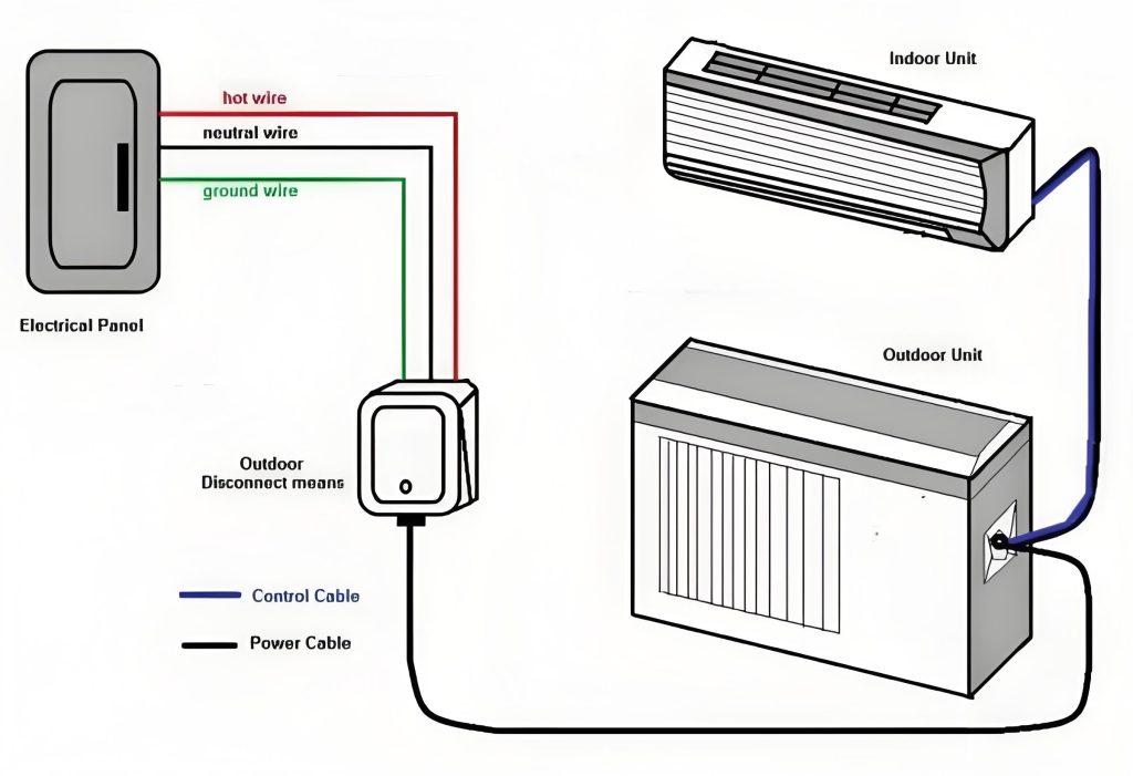
Air conditioning installation diagram
diagram split-type air conditioner
air conditioner unpackage
indoor unit installation
outdoor unit installation

Similar Posts

  • 第 3 項 – 「サプライリード」の定義の理解方法

    供給リード線: 機器を固定配線に接続するためのワイヤのセットで、a に収容されていますアプライアンスの内部またはアプライアンスに取り付けられたコンパートメント ここで強調する必要がある制限が 2 つあります。 1 つ目は、コンパートメント (通常はプラスチック製の電気ボックス) か、電線の配線に使用できる電化製品の凹んだ位置に収納する必要があることです。 2番目の条件はワイヤーです。ここでのワイヤーはコードとは異なります。このタイプのワイヤは、絶縁ワイヤ シースが 1 層のみの一般的なワイヤです。このタイプのワイヤのシースは通常、茶色または青色です。アース線の場合は黄緑色です。 下の写真に示すように、この部分は天井ファンの固定接続と電源接続を示しています。ロッドから出ている電線は、通常、固定配線(部屋の上部の配線や端子台)に直接接続できます。ワイヤのこの部分は通常、ワイヤ シースの層を備えた通常のワイヤです。上部のベルに入れることができるので、リードとみなすことができます。

  • 第 3 項 – 「クリアランス」の定義の理解方法

    クリアランス: 2 つの導電性部品間、または導電性部品と導電性部品間の空気中の最短距離アクセス可能な表面。 クリアランスは非常に重要な概念です。クリアランスを理解するには、完全に絶縁された物質はなく、空気も電気を通すことができるということをもう一度言う必要があります。電圧が非常に高い場合、電流は空気中に伝導します。雷雨時の落雷は、雷が空気中を伝導する典型的な例です。雷の電圧は非常に高いため、空気の非常に長い部分を突き破り、空気のこの部分が導電性になります。家電製品では、電圧は非常に低いですが、製品中には空気が多く含まれており、空気中にも電流が流れます。電圧が増加すると、電圧が空気を突き抜ける距離も長くなります。これにより、クリアランスの概念が生まれます。クリアランスの詳細な説明については、IEC 60664-1 (低電圧システム内の機器の絶縁調整 – パート 1: 原則、要件、およびテスト) を参照してください。 次の写真は電気的除去の経路をよく説明していると思います。 電圧の異なる2つの電極間や、充電部と電気製品使用者の手の間に隙間が生じる場合があります。上の写真の 2 つの電極を他の物体として想像するだけで済みます。 キー アクセス可能な発掘された金属部品 1 つ 2筐体3 接地されている金属部分4 出土した接近不可能な金属部分活電部 L1 と L2 は互いに分離されており、一部は開口部を備えたプラスチックの筐体で囲まれ、一部は空気に囲まれ、固体絶縁体と接触しています。構造内部にはアクセスできない金属が組み込まれています。金属カバーが 2 つあり、そのうちの 1 つはアースされています。絶縁クリアランスの種類基礎絶縁L1A L1D L2F 機能性絶縁体L1L2 補助絶縁DE FG 強化絶縁 L1K L1J L2I L1C 注記隙間 L1D または L2F が強化絶縁の隙間要件を満たしている場合、補助絶縁の隙間 DE または FG は測定されません。 L1CNOTE If the clearances L1D or…

  • Clause 3 – How to understand the definition of “built-in appliance”

    built-in appliance: fixed appliance intended to be installed in a cabinet, in a prepared recess in a wall or in a similar location. Here, because the appliance must be installed in a reserved position (usually a cubic space with only one side open), it is a fixed installation and can be regarded as a fixed…

  • 第 3 項 – 「クラス 0 アプライアンス」の定義の理解方法

    クラス 0 機器: 感電に対する保護が基礎絶縁のみに依存しており、導電性のアクセス可能な部品があったとしても、設備の固定配線内の保護導体に接続するための手段がなく、万一の場合に信頼できる機器。環境に設置された基礎断熱材の欠陥。注記 クラス 0 機器には、基礎絶縁の一部または全体を形成する絶縁材料のエンクロージャ、または適切な絶縁によって充電部から分離された金属エンクロージャのいずれかが備えられています。絶縁材の筐体を備えた機器に内部部品を接地するための設備がある場合、それはクラス I 機器またはクラス 0I 機器とみなされます。 この種の機器には保護接地装置がなく、同時に充電部を絶縁層で 1 層だけ包むか、絶縁層を使用して使用者を充電部から隔離します。ほとんどの国ではクラス 0 のアプライアンスを受け入れません。クラス 0 機器を受け入れられるのは、主電源電圧 (定格電圧) が日本などの 100 V と米国やメキシコなどの 120 V の一部の国だけです。ここで、同じ入力電力を達成するためには(たとえば、定格入力電力が 3000W のルームヒーター)、定格電圧が低いほど、対応する動作電流が大きくなることに言及する必要があります。逆に、定格電圧が高いと、それに対応する入力電流は小さくなります。大電流の場合、製品内の通電部品の発熱がより深刻になり、火災の可能性も高まるため、防火要件がより厳しくなります。低電流高電圧の場合、通電部の発熱はそれほど深刻ではありませんが、高電圧のため絶縁破壊の可能性が高くなり、感電防止の要件がより厳しくなります。 IEC 60335 シリーズの規格には、感電に対する保護に関して非常に高い要件が定められているのはこのためです。 IEC 60335 規格の主な作成者は、定格電圧 220 ~ 240V の国の専門家です。一方、米国の UL シリーズ規格には防火に関するさらに厳しい要件があります。通常、全ての充電部を基礎絶縁のみで保護するような機器は存在しません。感電に対する保護測定のほとんどは、二重絶縁または強化絶縁の要件を満たすことができるのが一般的です。もちろん基礎絶縁+接地保護構造もございます。一般的な状況は、電源コードのワイヤ シースが 1 層だけであり、デバイスの保護レベルは電源コードの基本絶縁、つまり最低の保護レベルのクラス 0 によって決まります。 次の 2 つの図は、クラス 0 アプライアンスの電源コードの情報を示しています。 1 つは回路図を示し、もう 1 つはプラグ付きの電源コードを示します。 次の図は、クラス…

  • 第3項 「第二種工事」の定義の見方

    ここで重点を置くのは、二重絶縁または強化絶縁の要件を満たすことができる機器の構造の一部です。したがって、クラス I アプライアンスにはクラス II 構造も含まれます。例:下図のオーブンでは金属シェルとプラスチック製スイッチノブが使用されています。使用者がスイッチノブに触れると、ノブは絶縁体でできているため接地できません。感電に対する保護はノブ自体の絶縁にのみ依存します。スイッチ内部の充電部とスイッチノブ軸間は基礎絶縁となっており、スイッチノブは補助絶縁を形成します。したがって、スイッチノブの位置はクラスII構造となります。    

  • 第3項「補助絶縁」の定義の見方

    補助絶縁:基礎絶縁が切れた場合に感電を防ぐために、基礎絶縁とは別に施される独立した絶縁 基礎断熱材の外側にあり、基礎断熱材から独立しており、通常はユーザーがアクセスできる断熱材。補助絶縁はその名のとおり追加的なものであり、基礎絶縁に追加する絶縁を指します。これには、この規格の基本原則、つまり二重保護の原則が関係します。いかなる危険に対しても、少なくとも 2 層または 2 セットの保護措置を講じる必要があります。いずれかの保護手段が失敗した場合でも、アプライアンスは別の保護層によって保護されます。ここでの追加絶縁の要件は、基礎絶縁が機能しなくなった場合に保護の役割を果たすことができる絶縁を考慮することです。ここでの保護は充電部の保護のみを目的としています。この規格の他の要件には、非充電部分に対する二重保護措置の要件が含まれます。 下図に示すように、基礎絶縁体の外表面(ここでは内部電線の電線被覆の外表面、またはスイッチのプラスチック材料表面と理解してください)から絶縁可能な箇所まで使用者が触れる部分(機器の底カバーや側面シェル)は、写真例から、機器の底カバーや側面シェルが補助絶縁材であると判断できます。これに対応して、サイドシェル内面に沿った内部リード線シースから外部ユーザーが触れる可能性のある場所までの沿面距離を補助絶縁とし、内部基礎絶縁からの最短直線距離と定義できます。空気を通って外部ユーザーが触れる可能性のある場所までの距離を補助絶縁クリアランスとして定義できます。ここでいうクリアランスとは、一般的にボトムシェルとサイドシェルの間の隙間を指します。