Clause 3 – How to Understand the Definition of “all-pole disconnection”

all-pole disconnection: disconnection of both supply conductors by a single initiating action or, for multi-phase appliances, disconnection of all supply conductors by a single initiating action
NOTE For multi-phase appliances, the neutral conductor is not considered to be a supply conductor.

Single-phase power: An AC power system composed of one live wire and one neutral wire.
Three-phase power: An AC power system composed of three live wires, with the same frequency and a phase difference of 120 degrees between each.

Single-phase power has two poles, which are the live wire/pole and the neutral wire/pole, generally, when we refer to multi-phase power, it is typically Three-phase power. Three-phase power has two type of connection such ass Star connection (Y connection) and Delta connection (Δ connection).

Star connection (Y connection): In a Star connection (Y connection), one end of each of the three load supply leads is joined to form a common neutral point. The other ends are connected to the three live wires, respectively.
Delta connection (Δ connection): The three load supply power leads are connected end-to-end, forming a closed loop, with the connection points respectively connected to the three live wires.
The supply conductors mentioned in the standard refer to the live wire and neutral wire in single-phase power, as well as all conductors in three-phase power except the neutral wire in a star connection. Each conductor is defined as a pole or supply conductor.

A disconnection is considered all-pole disconnection if a single action simultaneously disconnects both the live and neutral wires in a single-phase power system, or all supply conductors in a three-phase power system.
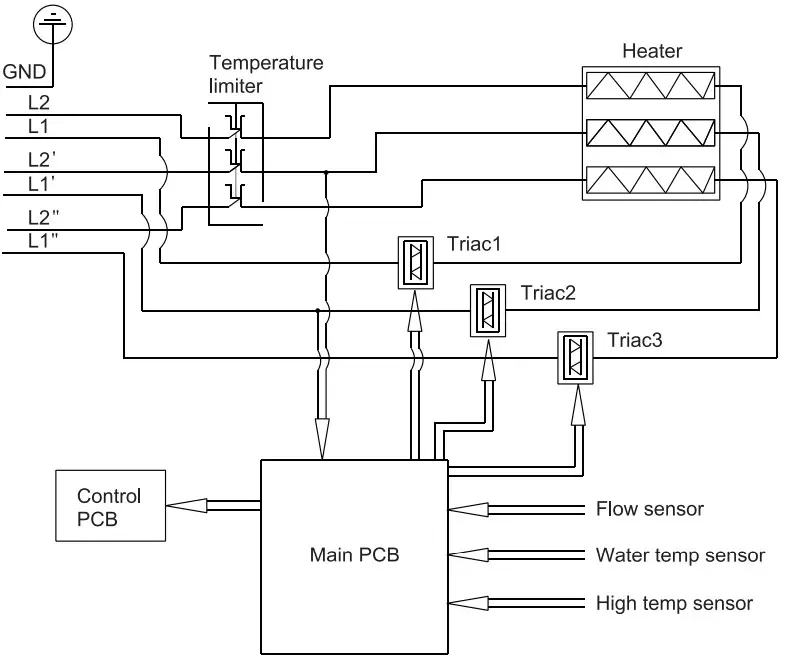
The purpose of defining all-pole disconnection is to provide protection against electric shock. In single-phase systems, both neutral and live conductors are considered live parts. Similarly, in three-phase systems, all live conductors are considered live parts. As shown in the below pictures, it shows the three-phase power system and single-phase power system appliance, the temperature limiter shown in pictures is an all-pole disconnection.
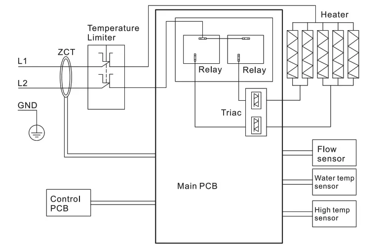
Electric tankless water heater electrical diagram
3 phase Electric tankless water heater electrical diagram

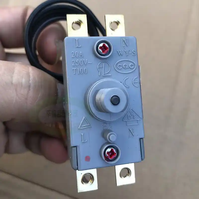
Below pictures show a thermal cut-out/ thermostat, you can find the all-pole disconnection diagram in its rating label.
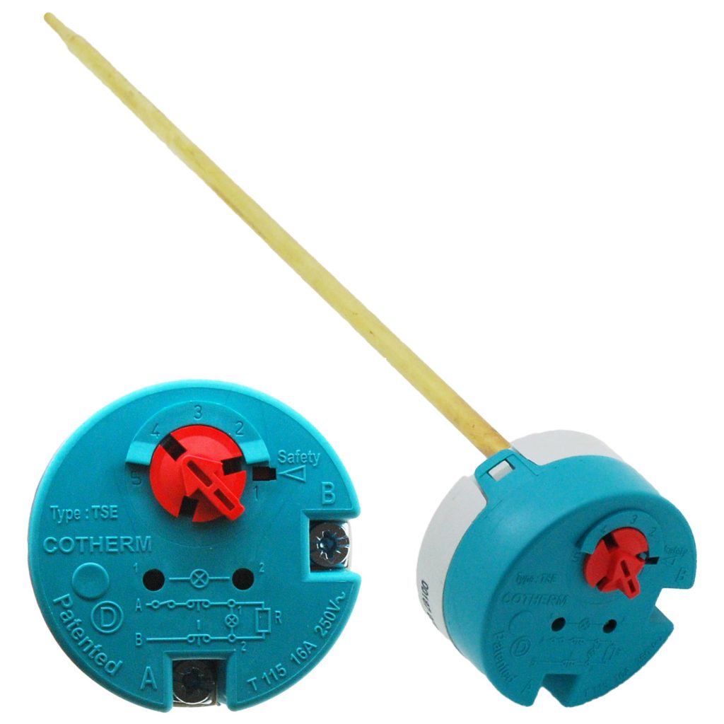
Immersion Thermostat & safety thermal cut-out in plumbing&heating water container

The bipolar thermal cut-out used in the kettle is shown in the figure below.
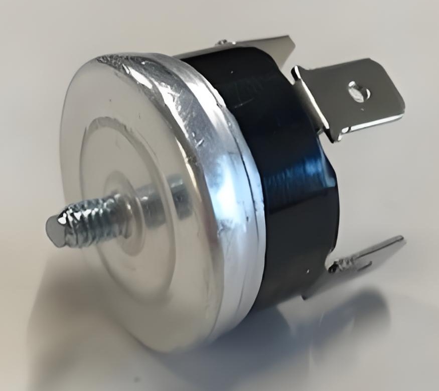
Dual Pole Thermal cut-out for Water boiler
Electric Water Dry Burn Overheat Protector, Bipolar Disconnection

The diagram below shows a three-pole thermal overload relay, which is an example of an all-pole disconnection device.
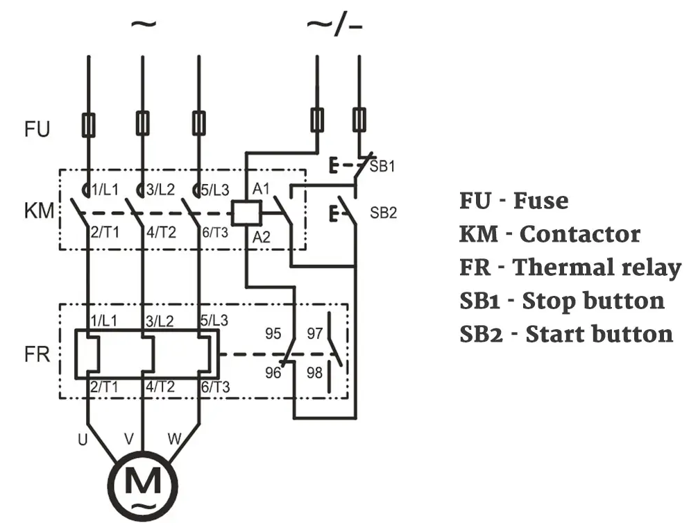
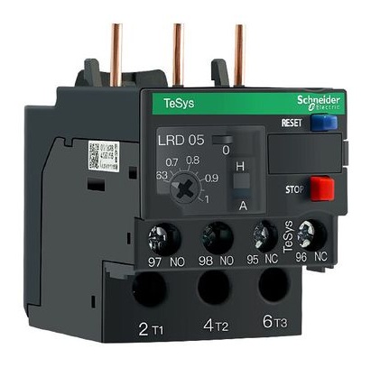
Thermal Overload Relay Working Principle Diagram
3-poles thermal overload relay

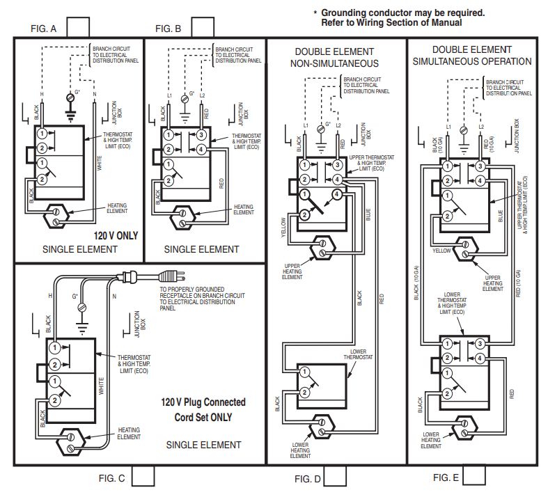
The wire connection diagram and the picture of thermal protective devices used in water heaters with container are shown in pictures below:
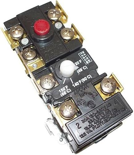
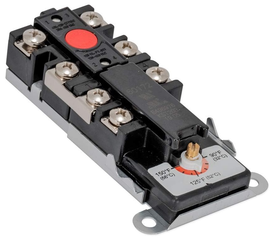
thermostat with temperature Adjustable one pole and 2-pole disconnection hand reset-1
thermostat with temperature Adjustable one pole and 2-pole disconnection hand reset
thermostat with temperature Adjustable one pole and 2-pole disconnection hand reset diagram

thermostat with temperature Adjustable one pole and 2-pole disconnection hand reset diagram.

Similar Posts

  • 第3項 「タイプX、タイプY、タイプZのアタッチメント」の定義の見方

    接続のタイプはアプライアンスのメーカーによって定義されます。一般に、これをタイプ X として定義することはまれです。これは、メーカーに不必要なリスクをもたらすことになるためです。一般にタイプ Y として定義されます。もちろん、電源コードが鋳造されている場合は、一般にタイプ Z として定義されます。次の図は、3 種類のアタッチメントの接続図を示しています。 タイプ X アタッチメント: 電源コードの接続は、アプライアンス内の特別に用意されたスペースで完了します。したがって、電源コードを交換する際には、端子台と内部配線以外の部分には触れません。電源コードを固定するネジは、通常の十字ネジまたは皿ネジです。電源コードの交換は管理可能な範囲内で行ってください。一般ユーザーが交換する電源コードは比較的シンプルで操作しやすいです。 タイプ Z アタッチメント、3.2.6 の説明と例を参照。 type Z attachment, see the explanation and examples in 3.2.6.

  • Clause 3 – How to understand the definition of “motor-operated appliance”

    motor-operated appliance: appliance incorporating motors but without any heating elementNote 1 to entry: Magnetically driven appliances are considered to be motor-operated appliances. Household electrical appliances usually use heating elements or motors to complete their designed functions. The main functions are heating, such as heating food or air, and rotation or mechanical movement of products, such…

  • 第 3 項 – 「通常の動作」の定義の理解方法

    通常動作: アプライアンスが主電源に接続されているときに通常の使用で動作する条件。 通常動作とは、通常、取扱説明書に定められた方法で動作している状態を指します。この動作モードは取扱説明書には記載されておらず、ユーザーは通常このように動作しませんが、標準で指定された方法で動作している状態を指す場合もあります。ここで、通常の動作はさまざまなパート II 標準で再定義される可能性があります。 冷蔵庫のパート 2 標準。通常の動作条件では、冷蔵庫の保管室を空にし、冷蔵庫の引き出しとドアを閉め、ユーザーが調整可能な温度制御を短絡または動作不能に設定する必要がある状態を示します。通常の動作は動作条件の 1 つにすぎません。通常の動作の標準的な定義は、最も過酷な動作条件を設定することを目的としている場合があります。

  • 第3項「機能絶縁」の定義の見方

    機能的絶縁: 電位の異なる導電性部分間の絶縁であり、機器が適切に機能するためにのみ必要です。 下の図は典型的な機能絶縁の図です。PCB の銅レール層の図に示されているように、ラベルの茶色の部分は電源活線 (電流ヒューズ間に接続されている 2 つの茶色の位置)、青色の部分です。接続は電力線の中性線であり、活線であり、中性線には 2 つの線の間に電圧差があるため、選択した銅線レールの青色の部分と選択した銅線レールの茶色の部分の間の最短距離になります。レール、つまり機能絶縁体です。実際、通常の動作では、下の写真の回路基板、銅レール上の電圧は多くの場所で同じではないため、機能絶縁の形成により、読者は動作電圧によって独自の回路分析を行うことができます。各部分。 AC 非同期モーターの一般的な巻線接続図は次の図のようになります。図のコンデンサが動作しているとき、コンデンサの両端の電圧は通常、製品の定格電圧よりも高くなります。たとえば、定格電圧が 220V の場合、動作中にマルチメータで測定されるコンデンサの両端の電圧は通常 300V を超えます。このとき、コンデンサの両端間の機能絶縁を評価する場合、300V以上の使用電圧を基準に評価する必要がありますが、実際にはコンデンサ自体の機能絶縁は一般的には可能ではありません。コンデンサの端子がコンデンサのケース内に封入されているため測定されます。測定できる箇所はコンデンサの2本のリード線の端子台です。 下図に示すように、端子台には左側に活線が接続され、右側に中性線が接続されています。赤い線の位置は機能絶縁体の沿面距離です(クリアランスもここで決定できます)。 下の図に示されているキャリパーの測定値は、PCB 上のアダプターの入力のライブ銅線と中性銅線の間の機能絶縁を表しています。 As shown in the figure below, the terminal block has the live wire connected on the left and the neutral wire connected on the right. The position of the red line is the creepage distance of the…

  • Clause 3 – How to understand the definition of “temperature limiter”

    temperature limiter: temperature-sensing device, the operating temperature of which may be either fixed or adjustable and which during normal operation operates by opening or closing a circuit when the temperature of the controlled part reaches a pre-determined value.Note 1 to entry: A temperature limiter does not make the reverse operation during the normal duty cycle…

  • 第 3 項 – 「安全絶縁変圧器」の定義の理解方法

    安全絶縁変圧器:安全超低電圧で機器または回路に供給することを目的とした、少なくとも二重絶縁または強化絶縁と同等の絶縁によって入力巻線が出力巻線から電気的に分離された変圧器 ここで言う変圧器は、機器や回路に電力を供給するために使用されます。最も一般的な変圧器は回路に電力を供給し、いくつかの変圧器は電化製品に電力を供給します。ここで重要となるのは入力巻線と出力巻線の絶縁対策であり、二重絶縁もしくは強化絶縁タイプ、または同等の絶縁が必要となります。この要件は、一次巻線と二次巻線が十分な絶縁を有することを保証することです。絶縁が十分であれば、変圧器の一次巻線と二次巻線間の絶縁は比較的安全です。二重の保護予防策。 スイッチの電源基板に使用される最初の種類のトランス。このタイプの変圧器は、同じ磁気コア上に一次巻線と二次巻線を重ね合わせます。したがって、一次側と二次側の間の沿面距離と電気的空間を確保するために、巻線を上下の端面に配置することはできません。以下の図に示すように、巻線は上下の端面から一定の距離にある必要があります。 安全絶縁トランスの全体図 安全絶縁トランスの全体図 The other is a drawer-type linear transformer, as shown below: