Clause 3 – How to Understand the Definition of “all-pole disconnection”

all-pole disconnection: disconnection of both supply conductors by a single initiating action or, for multi-phase appliances, disconnection of all supply conductors by a single initiating action
NOTE For multi-phase appliances, the neutral conductor is not considered to be a supply conductor.

Single-phase power: An AC power system composed of one live wire and one neutral wire.
Three-phase power: An AC power system composed of three live wires, with the same frequency and a phase difference of 120 degrees between each.

Single-phase power has two poles, which are the live wire/pole and the neutral wire/pole, generally, when we refer to multi-phase power, it is typically Three-phase power. Three-phase power has two type of connection such ass Star connection (Y connection) and Delta connection (Δ connection).

Star connection (Y connection): In a Star connection (Y connection), one end of each of the three load supply leads is joined to form a common neutral point. The other ends are connected to the three live wires, respectively.
Delta connection (Δ connection): The three load supply power leads are connected end-to-end, forming a closed loop, with the connection points respectively connected to the three live wires.
The supply conductors mentioned in the standard refer to the live wire and neutral wire in single-phase power, as well as all conductors in three-phase power except the neutral wire in a star connection. Each conductor is defined as a pole or supply conductor.

A disconnection is considered all-pole disconnection if a single action simultaneously disconnects both the live and neutral wires in a single-phase power system, or all supply conductors in a three-phase power system.
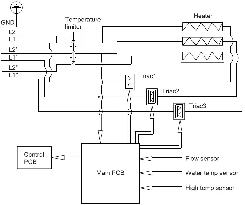
The purpose of defining all-pole disconnection is to provide protection against electric shock. In single-phase systems, both neutral and live conductors are considered live parts. Similarly, in three-phase systems, all live conductors are considered live parts. As shown in the below pictures, it shows the three-phase power system and single-phase power system appliance, the temperature limiter shown in pictures is an all-pole disconnection.
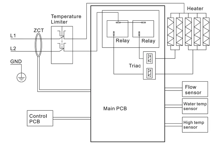
Electric tankless water heater electrical diagram
3 phase Electric tankless water heater electrical diagram

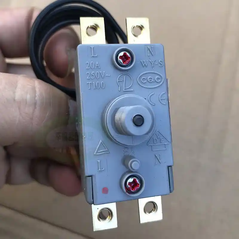
Below pictures show a thermal cut-out/ thermostat, you can find the all-pole disconnection diagram in its rating label.
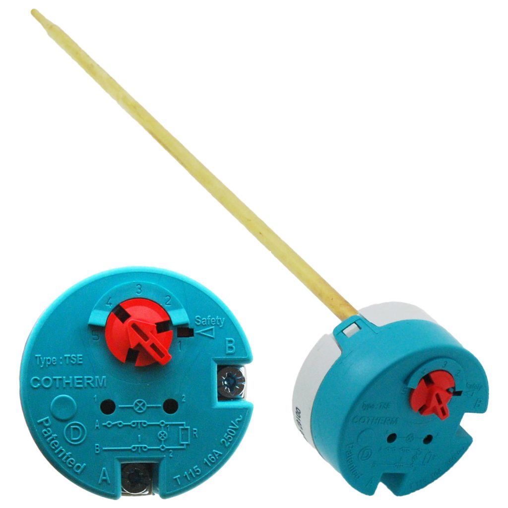
Immersion Thermostat & safety thermal cut-out in plumbing&heating water container

The bipolar thermal cut-out used in the kettle is shown in the figure below.
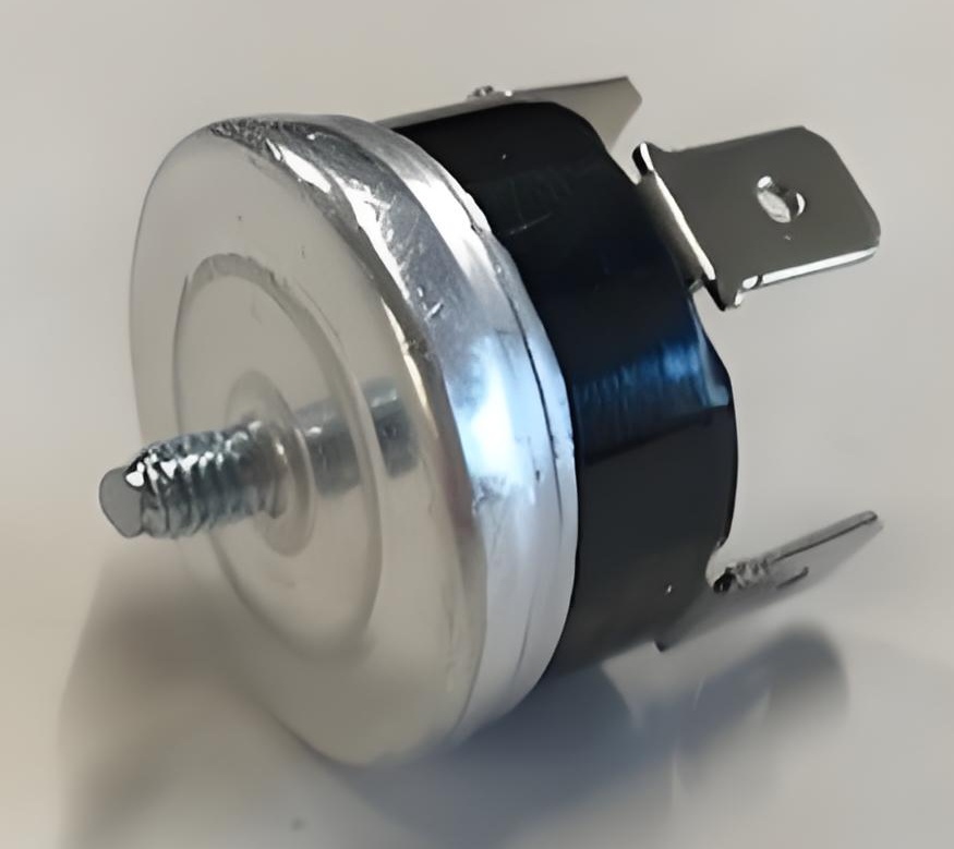
Dual Pole Thermal cut-out for Water boiler
Electric Water Dry Burn Overheat Protector, Bipolar Disconnection

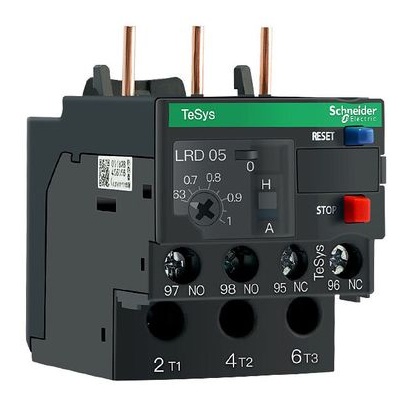
The diagram below shows a three-pole thermal overload relay, which is an example of an all-pole disconnection device.
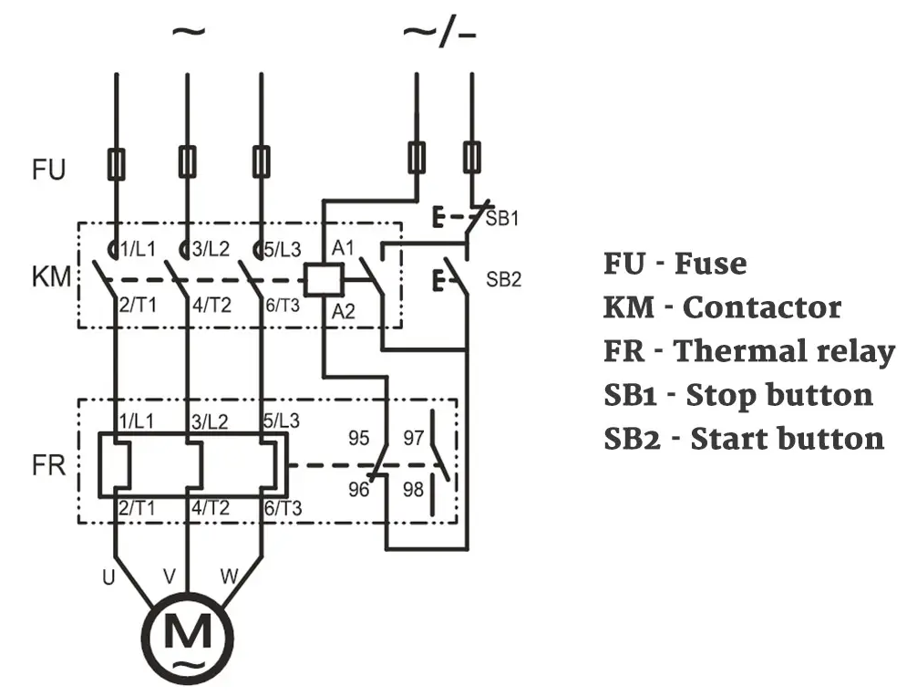
Thermal Overload Relay Working Principle Diagram
3-poles thermal overload relay

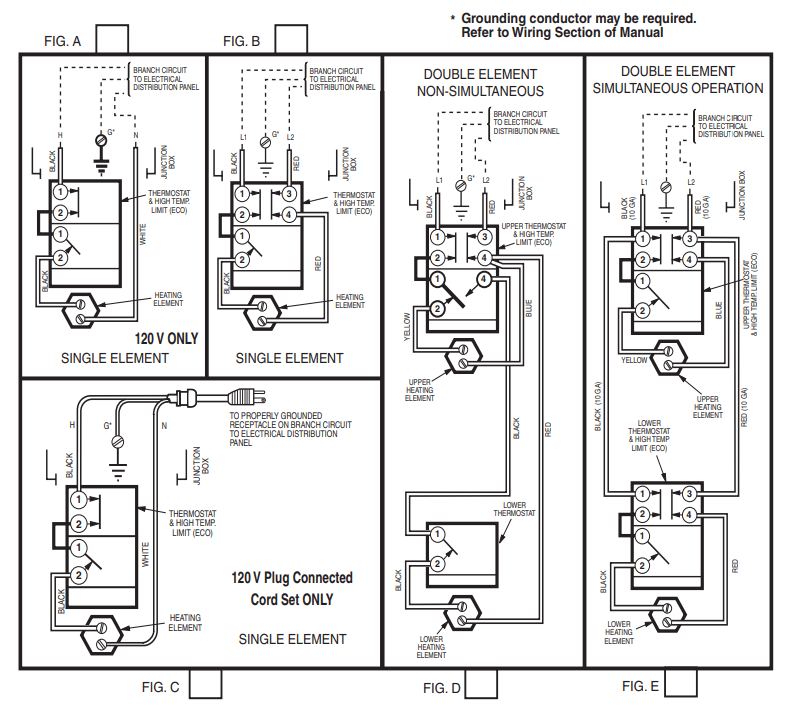
The wire connection diagram and the picture of thermal protective devices used in water heaters with container are shown in pictures below:
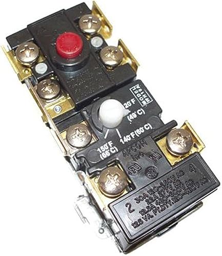
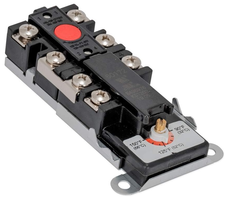
thermostat with temperature Adjustable one pole and 2-pole disconnection hand reset-1
thermostat with temperature Adjustable one pole and 2-pole disconnection hand reset
thermostat with temperature Adjustable one pole and 2-pole disconnection hand reset diagram

thermostat with temperature Adjustable one pole and 2-pole disconnection hand reset diagram.

Similar Posts

  • Clause 3 – How to understand the definition of “heating appliance”

    heating appliance: appliance incorporating heating elements but without any motor. Before introducing this definition, we need to briefly introduce the electric heating elements commonly used in household electrical appliances. PTC heating element: PTC (Positive Temperature Coefficient) heating elements are widely used for various heating applications because of their self-regulating properties and safety features. Here are…

  • Clause 3 – How to understand the definition of “protective device”

    protective device: device, the operation of which prevents a hazardous situation under abnormal operation conditions The standard emphasizes “abnormal operation” here. Only devices that operate under “abnormal operation” conditions can be defined as protective devices. Therefore, there are many types of protective devices, including overheating protection devices, overcurrent protection devices, and overpressure protection devices. Overheating…

  • ข้อ 3 – วิธีทำความเข้าใจคำจำกัดความของ “อุปกรณ์คลาส 0”

    เครื่องใช้ไฟฟ้าชนิดนี้ไม่มีอุปกรณ์ป้องกันสายดิน และในขณะเดียวกัน ฉนวนเพียงชั้นเดียวเท่านั้นที่พันชิ้นส่วนที่มีไฟฟ้า หรือใช้ฉนวนชั้นหนึ่งเพื่อแยกผู้ใช้ออกจากชิ้นส่วนที่มีไฟฟ้า ประเทศส่วนใหญ่ไม่ยอมรับเครื่องใช้ไฟฟ้า Class 0 เฉพาะบางประเทศที่มีแรงดันไฟฟ้าหลัก (แรงดันไฟฟ้า) 100V เช่น ญี่ปุ่น และ 120V เช่น สหรัฐอเมริกาและเม็กซิโก เท่านั้นที่ยอมรับเครื่องใช้ไฟฟ้า Class 0 จำเป็นต้องกล่าวถึงที่นี่ว่าเพื่อให้ได้พลังงานอินพุตเท่ากัน (เช่น เครื่องทำความร้อนในห้องที่มีกำลังไฟเข้าพิกัด 3000W) ยิ่งแรงดันไฟฟ้าที่กำหนดต่ำลง กระแสไฟทำงานที่สอดคล้องกันก็จะยิ่งมากขึ้นเท่านั้น ในทางตรงกันข้าม ถ้าแรงดันไฟฟ้าที่กำหนดสูง กระแสอินพุตที่สอดคล้องกันจะต่ำ ในกรณีที่มีกระแสไฟสูง การให้ความร้อนกับชิ้นส่วนที่นำกระแสไฟฟ้าในผลิตภัณฑ์จะรุนแรงมากขึ้น และความเป็นไปได้ที่จะเกิดเพลิงไหม้ก็จะมากขึ้น ดังนั้นข้อกำหนดในการป้องกันอัคคีภัยจึงเข้มงวดมากขึ้น ในกรณีของกระแสไฟฟ้าแรงต่ำและไฟฟ้าแรงสูง การให้ความร้อนของชิ้นส่วนที่นำกระแสไฟฟ้าไม่ร้ายแรง แต่เนื่องจากไฟฟ้าแรงสูง ความเป็นไปได้ที่ฉนวนจะแตกจะมีมากขึ้น และข้อกำหนดการป้องกันไฟฟ้าช็อตที่สอดคล้องกันจึงเข้มงวดมากขึ้น นี่คือสาเหตุที่มาตรฐานซีรีส์ IEC 60335 จึงมีข้อกำหนดสูงในการป้องกันไฟฟ้าช็อต ผู้เขียนหลักของมาตรฐาน IEC 60335 เป็นผู้เชี่ยวชาญจากประเทศที่มีแรงดันไฟฟ้า 220-240V ในขณะที่ชุดมาตรฐาน UL ของสหรัฐอเมริกามีข้อกำหนดที่เข้มงวดยิ่งขึ้นในการป้องกันอัคคีภัย โดยปกติไม่มีอุปกรณ์ดังกล่าวที่ชิ้นส่วนที่มีไฟฟ้าทั้งหมดได้รับการปกป้องด้วยฉนวนพื้นฐานเท่านั้น เป็นเรื่องปกติที่การวัดการป้องกันไฟฟ้าช็อตส่วนใหญ่ยังคงสามารถตอบสนองข้อกำหนดของฉนวนสองชั้นหรือฉนวนเสริมได้ แน่นอนว่ายังมีฉนวนพื้นฐานพร้อมโครงสร้างป้องกันสายดินด้วย สถานการณ์ทั่วไปคือมีปลอกสายไฟเพียงชั้นเดียวบนสายไฟ และระดับการป้องกันของอุปกรณ์ถูกกำหนดโดยฉนวนพื้นฐานของสายไฟ นั่นคือ…

  • Clause 3 – How to understand the definition of “battery-operated appliance”

    (IEC 60335-1 Ed. 5.1) battery-operated appliance: appliance deriving its energy from batteries enabling the appliance to perform its intended function without a mains connection.(IEC 60335-1 Ed. 6)battery-operated appliance: appliance deriving its energy from batteries enabling the appliance to perform its intended function without a supply connectionNote 1 to entry: A battery-operated appliance can have a…

  • ข้อ 3 – จะเข้าใจคำจำกัดความของ “ระยะห่างที่คืบคลาน” ได้อย่างไร

    คำจำกัดความของระยะห่างตามผิวฉนวนมาจากมาตรฐาน IEC 60664-1:2020 เนื่องจากเราต้องอธิบายระยะตามผิวฉนวน เราจึงต้องแสดงรูปภาพรูปที่ 4 ถึงรูปที่ 14 ในมาตรฐาน IEC 60664-1:2020 ในที่นี้ ผู้อ่านจะต้องพิจารณาอย่างรอบคอบถึงวิธีการกำหนด “X mm” หากมีร่องบนเส้นทางที่ทำให้เกิดระยะตามผิวฉนวน ก็จะมีสถานการณ์ร่องสะพาน โดยส่วนตัวผมคิดว่าสาเหตุหลักในการเชื่อมโยงคือการสะสมของสารมลพิษในร่อง มลพิษเหล่านี้ส่วนใหญ่เป็นฝุ่น และฝุ่นชื้นจะนำไฟฟ้าได้มากกว่า ดังนั้นการคัดลอกข้อความต้นฉบับของมาตรฐานจึงมีสมมติฐาน 3 ข้อดังต่อไปนี้: – ในกรณีที่ระยะห่างข้ามร่องน้อยกว่าความกว้าง X ที่ระบุ (ดูตารางที่ 1) ระยะห่างตามผิวฉนวนจะถูกวัดโดยตรงผ่านร่องและไม่คำนึงถึงรูปร่างของร่อง (ดูรูปที่ 4) – โดยที่ระยะห่างข้ามร่องเท่ากับหรือมากกว่าความกว้าง X ที่ระบุ (ดูตารางที่ 1) ระยะตามผิวฉนวนจะถูกวัดตามแนวโครงร่างของร่อง (ดูรูปที่ 5)– ช่องใดๆ ให้ถือว่าต่อเชื่อมด้วยตัวต่อฉนวนที่มีความยาวเท่ากับความกว้าง X ที่ระบุ และวางไว้ในตำแหน่งที่ให้ผลเสียมากที่สุด (ดูรูปที่ 6)– ระยะห่างจากอากาศและระยะห่างตามผิวฉนวนที่วัดระหว่างชิ้นส่วนซึ่งสามารถรับตำแหน่งที่แตกต่างกันโดยสัมพันธ์กัน ให้วัดเมื่อชิ้นส่วนเหล่านี้อยู่ในตำแหน่งที่ไม่เอื้ออำนวยที่สุดรูปที่ 4 – ข้ามร่องเงื่อนไข: เส้นทางที่พิจารณาประกอบด้วยร่องด้านขนานหรือบรรจบกันทุกความลึกที่มีความกว้างน้อยกว่า X…

  • ข้อ 3 – วิธีทำความเข้าใจคำจำกัดความของ “แรงดันไฟฟ้าในการทำงาน”

    : แรงดันไฟฟ้าสูงสุดที่ใช้กับชิ้นส่วนที่พิจารณาเมื่อจ่ายเครื่องใช้ไฟฟ้าที่แรงดันไฟฟ้าที่กำหนดและทำงานภายใต้การทำงานปกติ โดยมีอุปกรณ์ควบคุมและอุปกรณ์สวิตชิ่งอยู่ในตำแหน่งเพื่อเพิ่มมูลค่าสูงสุดหมายเหตุ 1 แรงดันไฟฟ้าในการทำงานคำนึงถึงแรงดันไฟฟ้าเรโซแนนซ์ หมายเหตุ 2 เมื่ออนุมานแรงดันไฟฟ้าที่ใช้งาน ผลกระทบของแรงดันไฟฟ้าชั่วคราวจะถูกละเว้น การ พิกัดแรงดันไฟฟ้า โดยทั่วไปคือแรงดันไฟฟ้าของตัวอย่างที่ทดสอบ อย่างไรก็ตาม ในวงจรภายในของเครื่องในสภาวะการทำงานปกติก็จะมีวงจรบางวงจรที่แรงดันไฟฟ้ามากกว่าหรือน้อยกว่าที่ พิกัดแรงดันไฟฟ้า พิกัดแรงดันไฟฟ้าพิกัดแรงดันไฟฟ้า ของแรงดันไฟฟ้า; แน่นอนว่าเครื่องใช้ไฟฟ้าสามารถมีแรงดันไฟฟ้าใช้งานได้มากกว่าหนึ่งแรงดันไฟฟ้า ตามมาตรฐาน บางครั้งจำเป็นต้องประเมินและพิจารณาว่าส่วนนี้ของวงจร (” ซึ่งส่วนที่พิจารณา” ในคำจำกัดความ) เป็นไปตามข้อกำหนดด้านความปลอดภัยของมาตรฐานโดยพิจารณาจากแรงดันไฟฟ้าที่ใช้งานหรือไม่ ในกรณีนี้เราต้องพิจารณาแรงดันไฟฟ้าสูงสุดที่อาจเกิดขึ้นในวงจรการทำงานตามที่กำหนดในมาตรฐาน ตามคำจำกัดความ เพื่อให้ได้ค่าสูงสุดของแรงดันไฟฟ้าที่ใช้งาน จำเป็นต้องจัดหาผลิตภัณฑ์ด้วยพิกัดแรงดันไฟฟ้า และทำงานภายใต้สภาวะการทำงานปกติ (หากผลิตภัณฑ์มีป้ายกำกับช่วงแรงดันไฟฟ้าที่กำหนด โดยทั่วไปจะใช้เป็นขีดจำกัดบนของช่วงแรงดันไฟฟ้าที่กำหนดเพื่อจ่ายแรงดันไฟฟ้า เช่น แรงดันไฟฟ้าที่กำหนด 220-240V กล่าวคือ 240V) และในขณะเดียวกันก็จำเป็นต้องตั้งค่าตัวควบคุมและอุปกรณ์สวิตชิ่งภายในผลิตภัณฑ์ให้จ่ายไฟตามแรงดันไฟฟ้าที่กำหนดและทำงานภายใต้สภาวะการทำงานปกติ แหล่งจ่ายไฟและทำงานภายใต้สภาวะการทำงานปกติ วัตถุประสงค์คือเพื่อให้แน่ใจว่าสามารถรับแรงดันไฟฟ้าในการทำงานสูงสุดได้ การประเมินจะขึ้นอยู่กับผลิตภัณฑ์ที่อยู่ในสภาวะการทำงานที่เลวร้ายที่สุด นอกจากนี้ การทดสอบจุดสูงสุดไม่ได้กล่าวถึงโดยเฉพาะที่นี่ ดังนั้นแรงดันไฟฟ้าที่ใช้งานจึงเป็นค่า RMS การกำหนดระยะตามผิวฉนวนในข้อ 29 จะขึ้นอยู่กับแรงดันไฟฟ้าที่ใช้งานเพื่อกำหนดขีดจำกัดระยะห่างตามผิวฉนวน ซึ่งจากนั้นต้องใช้แรงดันไฟฟ้าใช้งานที่ตำแหน่งเฉพาะในผลิตภัณฑ์ ข้อ 13 การทดสอบความทนทางไฟฟ้า แรงดันไฟฟ้าทดสอบที่ใช้กับโครงสร้างฉนวนจะขึ้นอยู่กับแรงดันไฟฟ้าที่ใช้งานด้วย rated voltage and…