Clause 3 – How to understand the definition of “electronic component”

electronic component: part in which conduction is achieved principally by electrons moving through a vacuum, gas or semiconductor.
NOTE Neon indicators are not considered to be electronic components.

Early vacuum tubes were components that allowed electrons to conduct in a vacuum and were the core components of old radios and televisions.
Electrons move through specific gases, colliding with gas molecules and causing them to emit light or conduct electricity. Examples include plasma display screens.
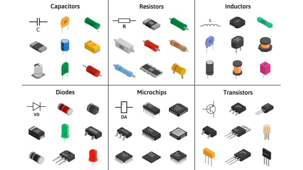
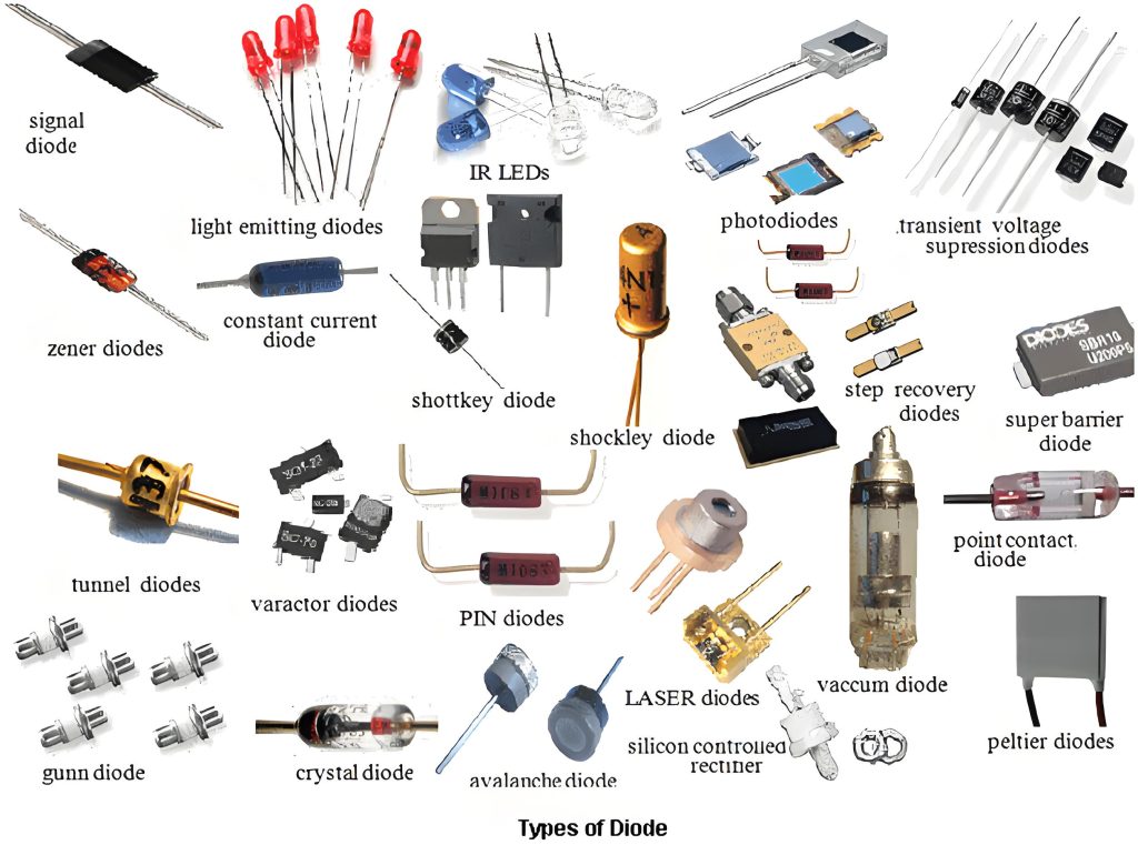
Electrons move through semiconductor materials such as silicon and germanium, and their conductivity can be precisely controlled through doping, electric fields, and other methods. Examples include transistors, integrated circuits (chips), diodes, triodes, MOSFETs (metal oxide semiconductor field effect transistors), and thermistors.
Note: “Neon indicator lights are not considered electronic components” is a very important qualification. Although neon lamps meet the definition of “electrons moving in a gas,” they are generally considered simple electric light sources.

The term “electronic component” generally refers to components (such as transistors and integrated circuits) that perform signal processing, control, and amplification functions in complex electronic circuits. Neon lamps are excluded because of their single function (indicating on/off) and simple structure.
Resistors, capacitors, and inductors are often referred to as passive components to distinguish them from active components (such as transistors and integrated circuits), which are not electronic components. Mechanical switches, thermostats, thermal cut-outs, pressure switches, motors, heating elements, batteries, and transformers are not electronic components.

This illustrates the subtle difference between theoretical and practical classifications.

Names and pictures of various common electronic components
type of diode
different packages of transistors

The main purpose of the definition of an electronic component is to show that electronic components are not completely reliable when they fulfil a protective function, but of course this unreliability is relative to non-electronic components.

Similar Posts

  • 第 3 項 – 「クリアランス」の定義の理解方法

    クリアランス: 2 つの導電性部品間、または導電性部品と導電性部品間の空気中の最短距離アクセス可能な表面。 クリアランスは非常に重要な概念です。クリアランスを理解するには、完全に絶縁された物質はなく、空気も電気を通すことができるということをもう一度言う必要があります。電圧が非常に高い場合、電流は空気中に伝導します。雷雨時の落雷は、雷が空気中を伝導する典型的な例です。雷の電圧は非常に高いため、空気の非常に長い部分を突き破り、空気のこの部分が導電性になります。家電製品では、電圧は非常に低いですが、製品中には空気が多く含まれており、空気中にも電流が流れます。電圧が増加すると、電圧が空気を突き抜ける距離も長くなります。これにより、クリアランスの概念が生まれます。クリアランスの詳細な説明については、IEC 60664-1 (低電圧システム内の機器の絶縁調整 – パート 1: 原則、要件、およびテスト) を参照してください。 次の写真は電気的除去の経路をよく説明していると思います。 電圧の異なる2つの電極間や、充電部と電気製品使用者の手の間に隙間が生じる場合があります。上の写真の 2 つの電極を他の物体として想像するだけで済みます。 キー アクセス可能な発掘された金属部品 1 つ 2筐体3 接地されている金属部分4 出土した接近不可能な金属部分活電部 L1 と L2 は互いに分離されており、一部は開口部を備えたプラスチックの筐体で囲まれ、一部は空気に囲まれ、固体絶縁体と接触しています。構造内部にはアクセスできない金属が組み込まれています。金属カバーが 2 つあり、そのうちの 1 つはアースされています。絶縁クリアランスの種類基礎絶縁L1A L1D L2F 機能性絶縁体L1L2 補助絶縁DE FG 強化絶縁 L1K L1J L2I L1C 注記隙間 L1D または L2F が強化絶縁の隙間要件を満たしている場合、補助絶縁の隙間 DE または FG は測定されません。 L1CNOTE If the clearances L1D or…

  • 第3項 「第3種建築物」の定義の見方

    クラスⅢ構造:感電に対する保護が安全特別低電圧に依存しており、安全特別低電圧以上の電圧が発生しない機器の一部注記 SELV での供給に加えて、基礎絶縁が必要な場合があります。 8.1.4を参照してください。注 2 機器の主要部分が SELV で動作し、取り外し可能な電源ユニットと一緒に納入される場合、機器のこの主要部分はクラス I 機器またはクラス II 機器のクラス III 構造とみなされます。 アプライアンスはプラグイン可能なアダプター (保護接地なし) によって電力を供給され、アダプターとアプライアンスは一緒にユーザーに配送されます。アダプターとアプライアンスは合わせてクラス II アプライアンスとして判断されます。アダプターはクラス II であるため、これによって感電に対する保護のクラスが決まります。ただし、機器 – ファンのみはクラス III 構造、つまりクラス II 機器内のクラス III 構造です。 もちろん、スイッチ電源 PCB が機器に組み込まれており、このスイッチ電源 PCB が SELV 回路を提供できるという別の状況もあります。そして、SELV回路部分はクラスII構造となっております。 Of course, there is another situation, that is, a switch power supply PCB is embedded in the appliance, and…

  • Clause 3 – How to understand the definition of “non-self-resetting thermal cut-out”

    non-self-resetting-thermal cut-out: thermal cut-out that requires a manual operation for resetting, or replacement of a part, in order to restore the current.NOTE Manual operation includes disconnection of the appliance from the supply mains. The thermal cut-out is equipped with a temperature-sensitive component, typically a bimetallic strip or a thermistor, which reacts to heat. As the…

  • Clause 3 – How to understand the definition of “stationary appliance”

    stationary appliance: fixed appliance or an appliance which is not a portable appliance. Stationary appliance includes fixed appliance and not a portable appliance. The characteristic of a stationary appliance is that once it is put into use, it will be placed in a fixed position. At the same time, the position of the appliances will…

  • 第 3 項 – 「通常の動作」の定義の理解方法

    通常動作: アプライアンスが主電源に接続されているときに通常の使用で動作する条件。 通常動作とは、通常、取扱説明書に定められた方法で動作している状態を指します。この動作モードは取扱説明書には記載されておらず、ユーザーは通常このように動作しませんが、標準で指定された方法で動作している状態を指す場合もあります。ここで、通常の動作はさまざまなパート II 標準で再定義される可能性があります。 冷蔵庫のパート 2 標準。通常の動作条件では、冷蔵庫の保管室を空にし、冷蔵庫の引き出しとドアを閉め、ユーザーが調整可能な温度制御を短絡または動作不能に設定する必要がある状態を示します。通常の動作は動作条件の 1 つにすぎません。通常の動作の標準的な定義は、最も過酷な動作条件を設定することを目的としている場合があります。

  • 第3項「機能絶縁」の定義の見方

    機能的絶縁: 電位の異なる導電性部分間の絶縁であり、機器が適切に機能するためにのみ必要です。 下の図は典型的な機能絶縁の図です。PCB の銅レール層の図に示されているように、ラベルの茶色の部分は電源活線 (電流ヒューズ間に接続されている 2 つの茶色の位置)、青色の部分です。接続は電力線の中性線であり、活線であり、中性線には 2 つの線の間に電圧差があるため、選択した銅線レールの青色の部分と選択した銅線レールの茶色の部分の間の最短距離になります。レール、つまり機能絶縁体です。実際、通常の動作では、下の写真の回路基板、銅レール上の電圧は多くの場所で同じではないため、機能絶縁の形成により、読者は動作電圧によって独自の回路分析を行うことができます。各部分。 AC 非同期モーターの一般的な巻線接続図は次の図のようになります。図のコンデンサが動作しているとき、コンデンサの両端の電圧は通常、製品の定格電圧よりも高くなります。たとえば、定格電圧が 220V の場合、動作中にマルチメータで測定されるコンデンサの両端の電圧は通常 300V を超えます。このとき、コンデンサの両端間の機能絶縁を評価する場合、300V以上の使用電圧を基準に評価する必要がありますが、実際にはコンデンサ自体の機能絶縁は一般的には可能ではありません。コンデンサの端子がコンデンサのケース内に封入されているため測定されます。測定できる箇所はコンデンサの2本のリード線の端子台です。 下図に示すように、端子台には左側に活線が接続され、右側に中性線が接続されています。赤い線の位置は機能絶縁体の沿面距離です(クリアランスもここで決定できます)。 下の図に示されているキャリパーの測定値は、PCB 上のアダプターの入力のライブ銅線と中性銅線の間の機能絶縁を表しています。 As shown in the figure below, the terminal block has the live wire connected on the left and the neutral wire connected on the right. The position of the red line is the creepage distance of the…