Clause 3 – How to understand the definition of “electronic component”

electronic component: part in which conduction is achieved principally by electrons moving through a vacuum, gas or semiconductor.
NOTE Neon indicators are not considered to be electronic components.

Early vacuum tubes were components that allowed electrons to conduct in a vacuum and were the core components of old radios and televisions.
Electrons move through specific gases, colliding with gas molecules and causing them to emit light or conduct electricity. Examples include plasma display screens.
Electrons move through semiconductor materials such as silicon and germanium, and their conductivity can be precisely controlled through doping, electric fields, and other methods. Examples include transistors, integrated circuits (chips), diodes, triodes, MOSFETs (metal oxide semiconductor field effect transistors), and thermistors.
Note: “Neon indicator lights are not considered electronic components” is a very important qualification. Although neon lamps meet the definition of “electrons moving in a gas,” they are generally considered simple electric light sources.

The term “electronic component” generally refers to components (such as transistors and integrated circuits) that perform signal processing, control, and amplification functions in complex electronic circuits. Neon lamps are excluded because of their single function (indicating on/off) and simple structure.
Resistors, capacitors, and inductors are often referred to as passive components to distinguish them from active components (such as transistors and integrated circuits), which are not electronic components. Mechanical switches, thermostats, thermal cut-outs, pressure switches, motors, heating elements, batteries, and transformers are not electronic components.

This illustrates the subtle difference between theoretical and practical classifications.
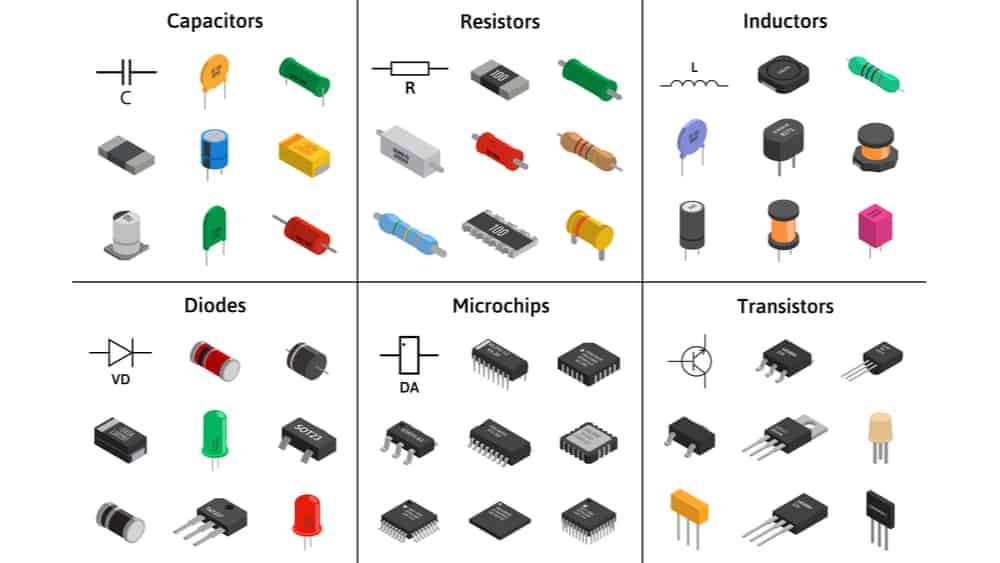
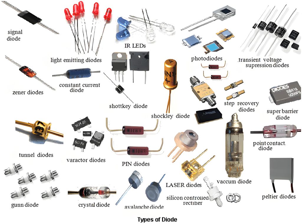
Names and pictures of various common electronic components
type of diode
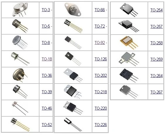
different packages of transistors

The main purpose of the definition of an electronic component is to show that electronic components are not completely reliable when they fulfil a protective function, but of course this unreliability is relative to non-electronic components.

Similar Posts

  • Clause 3 – How to Understand the Definition of “Intentionally Weak Part”

    intentionally weak part: A part intended to rupture under abnormal operating conditions to prevent the occurrence of a condition that could impair compliance with this standard.NOTE: Such a part may be a replaceable component, such as a resistor or capacitor, or a part of a component to be replaced, such as an inaccessible thermal link

  • 第3項 「タイプZアタッチメント」の定義の見方

    タイプ Z アタッチメント: 製造元、そのサービス代理店、または同様の資格を持つ担当者が交換を行うための電源コードの取り付け方法。 一部の製品の電源コードは製品と一体成型されており、一般的な工具では取り外すことができません。または、一部の電化製品の電源コードは、接続後に熱硬化性材料によって電化製品にキャストされます。これらの同様の構造では、電源コードの交換作業を完了するには、電源コードに接続されている材料を破壊する必要があります。例:図のように水中ポンプのシェルに電源コードをエポキシ樹脂で流し込んでいます。電源コードを交換する場合は、注型エポキシ樹脂を破壊する必要があります。 ウォーターポンプ内部図

  • 第3項 「タイプX、タイプY、タイプZのアタッチメント」の定義の見方

    接続のタイプはアプライアンスのメーカーによって定義されます。一般に、これをタイプ X として定義することはまれです。これは、メーカーに不必要なリスクをもたらすことになるためです。一般にタイプ Y として定義されます。もちろん、電源コードが鋳造されている場合は、一般にタイプ Z として定義されます。次の図は、3 種類のアタッチメントの接続図を示しています。 タイプ X アタッチメント: 電源コードの接続は、アプライアンス内の特別に用意されたスペースで完了します。したがって、電源コードを交換する際には、端子台と内部配線以外の部分には触れません。電源コードを固定するネジは、通常の十字ネジまたは皿ネジです。電源コードの交換は管理可能な範囲内で行ってください。一般ユーザーが交換する電源コードは比較的シンプルで操作しやすいです。 タイプ Z アタッチメント、3.2.6 の説明と例を参照。 type Z attachment, see the explanation and examples in 3.2.6.

  • 第 3 項 – 「クラス 0I アプライアンス」の定義の理解方法

    クラス 0I 機器:全体に少なくとも基礎絶縁があり、接地端子が組み込まれているが、接地線のない電源コードと接地接点のないプラグを備えた機器 機器には外部保護導体(保護接地導体)を接続するための端子がありますが、固定配線には機器と保護導体を接続するための電線がなく、機器内部に接地導通を伝えるための配線や構造が設けられている場合があります。 日本では、以下のようなクラス0I機器専用のプラグがあります。 私の理解では、現在、クラス 0I 機器を使用しているのは日本だけです。通常、電源コードにはアース線が付いていますが、プラグ内のアースピンによってアースは行われません。代わりに、ツールを使用して別の端子または接地リングを接続し、効果的な接地を実現します。同様に、アプライアンスにもアース端子があります。設置前、この端子は外部配線に接続されておらず、通常は使用中および設置中に接続されます。

  • 第3項「機能絶縁」の定義の見方

    機能的絶縁: 電位の異なる導電性部分間の絶縁であり、機器が適切に機能するためにのみ必要です。 下の図は典型的な機能絶縁の図です。PCB の銅レール層の図に示されているように、ラベルの茶色の部分は電源活線 (電流ヒューズ間に接続されている 2 つの茶色の位置)、青色の部分です。接続は電力線の中性線であり、活線であり、中性線には 2 つの線の間に電圧差があるため、選択した銅線レールの青色の部分と選択した銅線レールの茶色の部分の間の最短距離になります。レール、つまり機能絶縁体です。実際、通常の動作では、下の写真の回路基板、銅レール上の電圧は多くの場所で同じではないため、機能絶縁の形成により、読者は動作電圧によって独自の回路分析を行うことができます。各部分。 AC 非同期モーターの一般的な巻線接続図は次の図のようになります。図のコンデンサが動作しているとき、コンデンサの両端の電圧は通常、製品の定格電圧よりも高くなります。たとえば、定格電圧が 220V の場合、動作中にマルチメータで測定されるコンデンサの両端の電圧は通常 300V を超えます。このとき、コンデンサの両端間の機能絶縁を評価する場合、300V以上の使用電圧を基準に評価する必要がありますが、実際にはコンデンサ自体の機能絶縁は一般的には可能ではありません。コンデンサの端子がコンデンサのケース内に封入されているため測定されます。測定できる箇所はコンデンサの2本のリード線の端子台です。 下図に示すように、端子台には左側に活線が接続され、右側に中性線が接続されています。赤い線の位置は機能絶縁体の沿面距離です(クリアランスもここで決定できます)。 下の図に示されているキャリパーの測定値は、PCB 上のアダプターの入力のライブ銅線と中性銅線の間の機能絶縁を表しています。 As shown in the figure below, the terminal block has the live wire connected on the left and the neutral wire connected on the right. The position of the red line is the creepage distance of the…

  • 第3項 – 「定格電力入力範囲」の定義の見方

    定格電力入力範囲: メーカーによってアプライアンスに割り当てられた電力入力範囲。下限値と上限値で表されます。 この定義は定格電圧範囲に対応しています。つまり、定格電力入力には上限と下限の範囲がラベル付けされています。例:定格電圧範囲AC220~240V、定格入力電力範囲2000~2200Wの石英管ルームヒーター