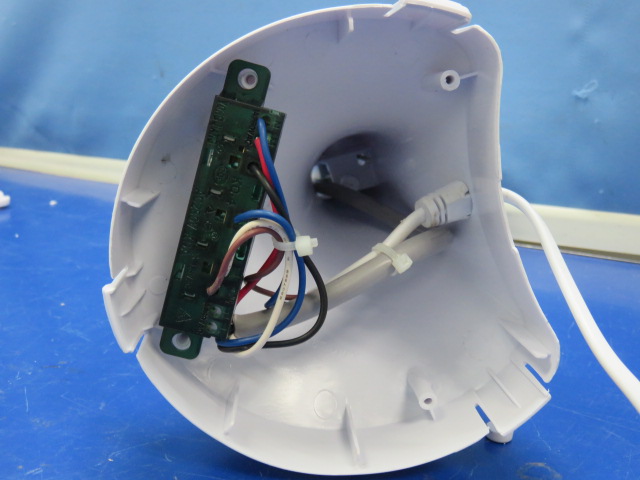
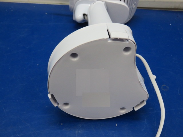
As shown in the following two pictures(fan), the internal lead wires sheath in the left picture is basic insulation, and the bottom plate of the outer casing is additional insulation.
The following circuit board picture has an animation effect. The right side of the dotted line is the inaccessible part with a working voltage of 220-240V, and the left side of the dotted line is the accessible part with a maximum working voltage of 24V (assuming that the structure at the location of the dotted line has met the requirements of double insulation or reinforced insulation). In order to ensure effective isolation, generally speaking, the wires on the right side of the dotted line (red and blue internal wires) cannot touch the relatively thin internal wires on the left. The wire sheath of the right wire is basic insulation, because the wire sheath is in direct contact with the live parts and is the first layer of protection for the live parts. The wire sheath of the left wire can only be defined as supplementary insulation, but whether it meets the requirements for supplementary insulation in clause 29.3 will be analyzed when introducing clause 29.3. It should be noted here that the wire sheath of the left wire cannot be defined as basic insulation, and the wire sheath of the right wire cannot be supplementary insulation.
motor-operated appliance: appliance incorporating motors but without any heating elementNote 1 to entry: Magnetically driven appliances are considered to be motor-operated appliances. Household electrical appliances usually use heating elements or motors to complete their designed functions. The main functions are heating, such as heating food or air, and rotation or mechanical movement of products, such…
8.1.5 Live parts of built-in appliances, fixed appliances, and appliances delivered in separate units shall be protected by at least basic insulation before installation or assembly. Compliance is checked by inspection and the test in 8.1.1.Why is this requirement in place? I believe there are three types of hazards that require protection. The first is…
accessible part: part or surface that can be touched by means of test probe B of IEC 61032, and if the part or surface is metal, any conductive part connected to it.NOTE Accessible non-metallic parts with conductive coatings are considered to be accessible metal parts. There are some parts or surfaces in the appliance that…
combined appliance: appliance incorporating heating elements and motors. We know that this standard mainly protects against the following five types of dangers, which are electric shock, mechanical damage from moving parts, thermal damage (such as burns), fire damage, chemical and biological damage. Generally speaking, thermal damage is caused by electric heating elements, and mechanical damage…
クラスⅢ構造:感電に対する保護が安全特別低電圧に依存しており、安全特別低電圧以上の電圧が発生しない機器の一部注記 SELV での供給に加えて、基礎絶縁が必要な場合があります。 8.1.4を参照してください。注 2 機器の主要部分が SELV で動作し、取り外し可能な電源ユニットと一緒に納入される場合、機器のこの主要部分はクラス I 機器またはクラス II 機器のクラス III 構造とみなされます。 アプライアンスはプラグイン可能なアダプター (保護接地なし) によって電力を供給され、アダプターとアプライアンスは一緒にユーザーに配送されます。アダプターとアプライアンスは合わせてクラス II アプライアンスとして判断されます。アダプターはクラス II であるため、これによって感電に対する保護のクラスが決まります。ただし、機器 – ファンのみはクラス III 構造、つまりクラス II 機器内のクラス III 構造です。 もちろん、スイッチ電源 PCB が機器に組み込まれており、このスイッチ電源 PCB が SELV 回路を提供できるという別の状況もあります。そして、SELV回路部分はクラスII構造となっております。 Of course, there is another situation, that is, a switch power supply PCB is embedded in the appliance, and…
non-self-resetting-thermal cut-out: thermal cut-out that requires a manual operation for resetting, or replacement of a part, in order to restore the current.NOTE Manual operation includes disconnection of the appliance from the supply mains. The thermal cut-out is equipped with a temperature-sensitive component, typically a bimetallic strip or a thermistor, which reacts to heat. As the…