Clause 3 – How to understand the definition of “non-self-resetting thermal cut-out”

non-self-resetting-thermal cut-out: thermal cut-out that requires a manual operation for resetting, or replacement of a part, in order to restore the current.
NOTE Manual operation includes disconnection of the appliance from the supply mains.

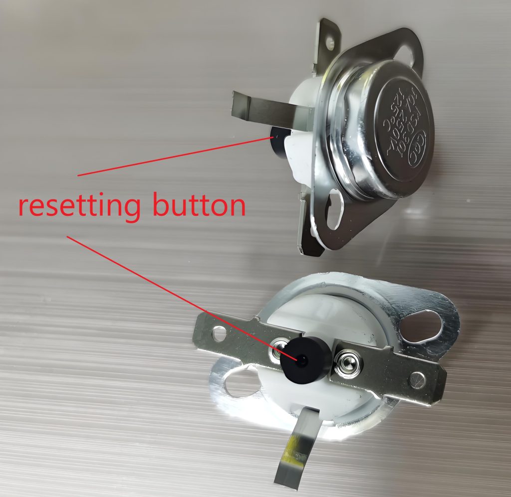
The thermal cut-out is equipped with a temperature-sensitive component, typically a bimetallic strip or a thermistor, which reacts to heat. As the temperature of the appliance or circuit increases, the bimetallic strip bends or the resistance of the thermistor changes. When the heat decreases and the temperature drops, the bimetallic strip will deform, reconnecting the circuit and completing the self-resetting action. The non- self-resetting thermal cut-out we are discussing here can be reset, but it cannot perform the reset action by itself.
For example, a non-self-resetting thermal cut-out that needs to be reset manually requires pressing a button. I won’t explain how this works here, you can google it yourself.

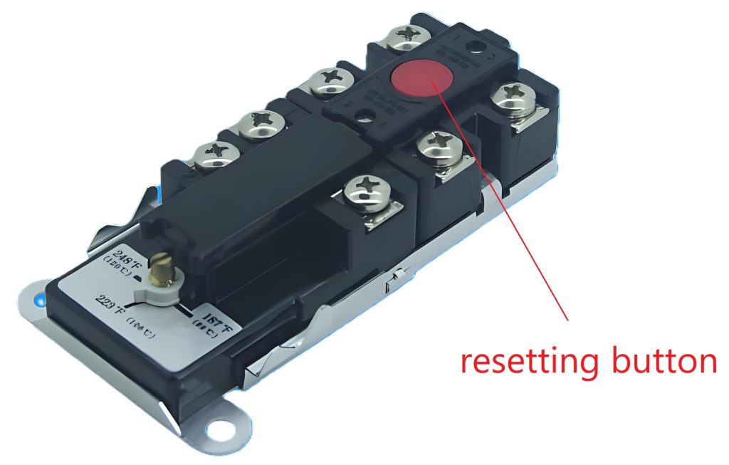
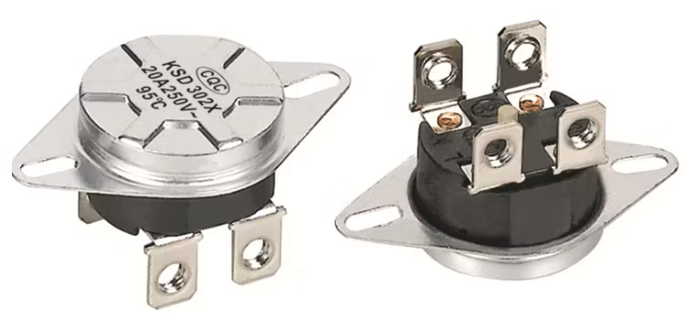
Another type of thermal cut-out is the one that needs to be disconnected from the power/main supply in order to complete the resetting action. Typical non-self-resetting thermal cut-outs(voltage maintained non-self-resetting thermal cut-out) are used in motors and are shown in the figure below:

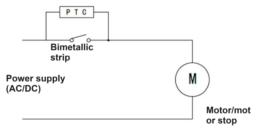
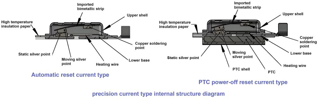
Its working principle can be explained by the figure below. When the bimetallic strip disconnects the circuit, since the PTC is connected to the circuit and is generating heat still, the bimetallic strip is still in a relatively hot state and cannot be reset. When the power is disconnected (for example, the plug is unplugged), the PTC does not generate heat and can be reset after a period of time.

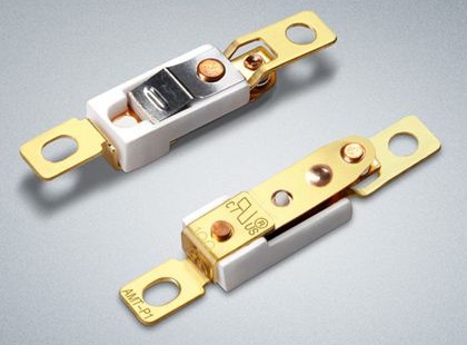
Its internal structure is shown below:

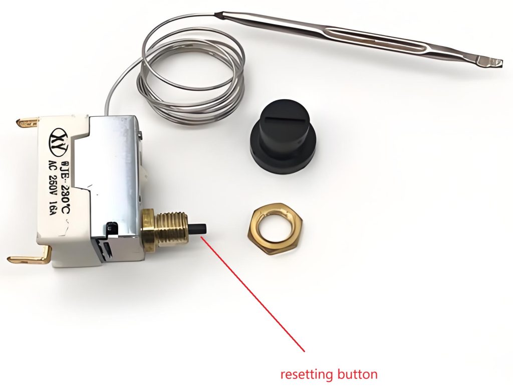
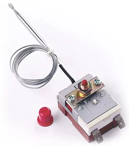
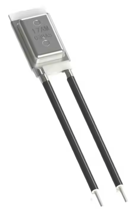
Another voltage maintained non-self-resetting thermal cut-out are used in room heater or hair dryer are shown in the figure below:

Similar Posts

  • Clause 3 – How to understand the definition of “electronic component”

    electronic component: part in which conduction is achieved principally by electrons moving through a vacuum, gas or semiconductor.NOTE Neon indicators are not considered to be electronic components. Early vacuum tubes were components that allowed electrons to conduct in a vacuum and were the core components of old radios and televisions.Electrons move through specific gases, colliding…

  • Clause 3 – How to understand the definition of “self-resetting thermal cut-out”

    self-resetting thermal cut-out: thermal cut-out that automatically restores the current after the relevant part of the appliance has cooled down sufficiently In the definition there is a clear mention, when the temperature is cooled to a certain degree, in fact, its intention is to control the temperature is not too high, when the temperature is…

  • 第3項 「定格電圧範囲」の定義の見方

    定格電圧範囲:メーカーによって家電製品に割り当てられた電圧範囲。下限値と上限値で表されます。 この定義は、の定義を拡張したものです 定格電圧定格電圧 定格電圧、ただし、定格電圧が定義されていることはほとんどありません。 例えば、ヨーロッパの全EU加盟国市場を対象市場として設計された製品の場合、ほとんどのEU加盟国の商用電圧はAC 230Vですが、別途規定があればAC 240Vである国もあります定格電圧がAC230VまたはAC240Vの場合、本製品は国の定格電圧と異なる商用電圧では使用できません。このような状況を考慮し、AC220VとAC230V、AC240VをカバーするAC220~240Vの範囲で定格電圧を規定し、これら3つの商用電圧の国でも対応製品を使用できるようにしました。ここでは、AC220-240V または 220-240V~ がより一般的な形式です。 220 ~ 230V ~、380V ~ 415V ~、または 100 ~ 240V ~ (この状況のほとんどは、アダプターの定格入力電圧で電力供給されるアダプターの使用時に発生します) などもあります。製品の定格電圧は範囲が設定されているため、その電圧範囲における安全要件を規格に従って評価する必要があります。 For example, a product designed for the target market for the whole of Europe’s all EU member states market, most of the EU member states of the utility voltage is AC 230V,…

  • |

    Clause 3 – How to understand the definition of “room temperature”

    room temperature: ambient temperature specified in the general conditions for the tests.Note 1 to entry: The ambient temperature is specified in 5.7. This item comes from standard IEC 60335-1:2020 edition 6.0. In commented version (CMV) of the official standard IEC 60335-1:2020 edition 6.0 allows the user to identify the changes made to the previous edition…

  • 第 3 項 – 「保護インピーダンス」の定義の理解方法

    保護インピーダンス: 通常の使用時および機器の故障の可能性がある状態での電流が安全な値に制限されるように、クラス II 構造の充電部分とアクセス可能な導電部分の間に接続されたインピーダンス。 ケース1:最初のケースは、通常、アダプター駆動の製品など、低電圧電源を必要とする状況です。アダプターの出力電圧はDC12V、DC24V、またはDC5Vです。これらの低電圧部品は、変圧器の変圧と整流器電流の整流によって得られるため、一般にユーザーが触れることができます。したがって、高電圧部分と電圧部分を効果的に絶縁する必要があります。当社の一般的なスイッチング電源基板では、EMC 伝導テストを実施すると、トランスの一次側で発生した干渉が一次側と二次側の間の寄生容量を通過し、150k~30MHz の伝導性干渉が発生して二次側に到達します。ここでは、Y コンデンサを使用して干渉信号を電源に戻し、干渉を相殺するループを形成します。そうしないと、導通テストが不合格になります。ここでの Y コンデンサは保護インピーダンスを形成します。下図の赤いボックスで選択された 2 つの Y コンデンサが保護インピーダンスです。 下図はマイナスイオン発生器の回路図です。赤い四角形で選択された 2 つの抵抗は、一般的な保護インピーダンスです。 下の図のCY1とCY2は保護インピーダンスですか? 規格の定義から、保護インピーダンスは接地が存在するクラス II 構造で使用されます。ここでの接地が保護接地として定義されている場合、保護インピーダンスはクラス II 構造で使用され、ここではクラス I 構造であるため、明らかに CY1 と CY2 を保護インピーダンスとして定義できません。ここでの接地が機能接地として定義されている場合、2 つの問題があります。まず、これはクラス I 構造であるため、CY1 と CY2 は保護インピーダンスとして定義できません。次に、クラス II 構造の場合、CY1 と CY2 を保護インピーダンスとして定義でき、保護インピーダンスの関連要件を満たす必要があります。私の個人的な意見は、CY1 と CY2 は保護インピーダンスではなく、直接基礎絶縁とみなしてよいと考えています。結局のところ、回路図に示されている設計は規格に受け入れられないということでしょうか?そしてnbsp; それらが保護インピーダンスである場合、どちらが第 22.42 条「保護インピーダンスは少なくとも 2 つの別個のコンポーネントで構成されなければならない」に準拠する必要があります。 From the definition of the standard, the…

  • 第3項 – 「安全特別低電圧」の定義の見方

    安全特別低電圧: 導体間および導体とアース間の電圧は 42 V を超えず、無負荷電圧は 50 V を超えない 安全特別低電圧が主電源から得られる場合、安全絶縁を介する必要があります。 注 1 指定された電圧制限は、安全絶縁変圧器が定格電圧で供給されるという前提に基づいています。注 2 安全特別低電圧は SELV とも呼ばれます。 はじめに-1 。また、本項で定義する「安全」は、SELV を使用者が直接触れることができる絶対的な安全を意味するものではありません。ユーザーは、セクション 8.1.4 の要件を満たす SELV 回路のみに触れることができます。この電圧は通常、安全絶縁変圧器または別の巻線を備えたコンバータを通じて電圧を降圧することによって得られます。通常、これは安全絶縁変圧器を通じて得られます。ここで、別個の巻線を備えた安全絶縁変圧器またはコンバータは、一次巻線と二次巻線が物理的に構造的に分離されていることを保証できます。つまり、一次巻線と二次巻線が直接接触しないようにすることができます。この別巻線による回路分離に対応した電圧調整方式の一般的な例は、220V 回路に抵抗とコンデンサを直列に並列接続する RC 降圧方式です。 RC降圧方式では、回路内で高圧部と低圧部が接続されます。明らかに、物理的手段によって回路を分離する前者の方法の方が安全です。単純な物理的分離である場合でも、安全要件を満たすことはできません。規格で要求される絶縁は二重絶縁または強化絶縁の要件を満たす必要があります。簡単に言うと、高電圧部分と低電圧部分の間に非常に単純な絶縁(低温耐性を持つ薄いプラスチックシートなど)がある場合、この絶縁は高温または高電圧条件下で破損しやすく、基本的には絶縁できません。このプラスチックシートの層は絶縁の役割を果たしますが、高電圧回路と低電圧回路を物理的に分離することもあります。二重絶縁と強化絶縁の絶縁要件も二重保護の手段です。下の図に示すように、トランスには一次巻線と二次巻線を分離するためにディスクに垂直に配置された 3 つのプラスチック ブラケットがあり (一次巻線と二次巻線の外側には青いプラスチック テープが巻かれています)、一次巻線と二次巻線は物理的に隔離されています。 下の図に示すように、トランスには中央の一次巻線と二次巻線に黄色いテープが巻かれています。強化絶縁の沿面距離要件を満たしているかどうかを確認するには、2 つの巻線間の黒いブラケットの沿面距離に特に注意を払う必要があります。そうでない場合、その変圧器は安全絶縁変圧器として判断できません。 安全絶縁トランスの構造については次回詳しく説明します。 As shown in the figure below, the transformer has yellow tape wrapped around the primary and secondary windings in the…