Clause 3 – How to understand the definition of “user maintenance”

user maintenance: any maintenance operation stated in the instructions for use, or marked on the appliance, that the user is intended to perform.

Allowed user-executed operations, the operation guideline was given in user manual, and it could be showed in enclosure of appliance. Since it is a allowed user-executed operation, then additional protective method should be included in appliance to against hazards; moreover, we must consider that the user performing the maintenance operation does not have much experience with hazard protection, as well as reasonable misuse by the user during maintenance. We need to differentiate between maintenance and repairs; repairs are performed by professionals, and not much protection is needed for the repairers as they are more specialised.

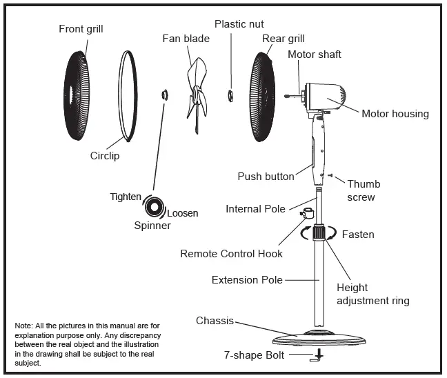
Such as floor standing fan, usually the user will be allowed to disassemble and clean it, and the manual will give detailed instructions for disassembly and cleaning accordingly. A snippet of the instruction manual is shown below:
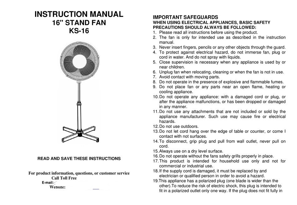
user manual cover page for floor standing fan
Floor standing fan installation diagram

This is a typical type of user maintenance.
The standard refer to definition – user maintenance in clause 7.12, clause 15.1, clause 22.14, clause 23.3, and clause 28.1, which are primarily concerned with avoiding or minimising the hazards that can occur during user maintenance.

Similar Posts

  • Clause 3 – How to understand the definition of “temperature limiter”

    temperature limiter: temperature-sensing device, the operating temperature of which may be either fixed or adjustable and which during normal operation operates by opening or closing a circuit when the temperature of the controlled part reaches a pre-determined value.Note 1 to entry: A temperature limiter does not make the reverse operation during the normal duty cycle…

  • 第 3 項 – 「安全絶縁変圧器」の定義の理解方法

    安全絶縁変圧器:安全超低電圧で機器または回路に供給することを目的とした、少なくとも二重絶縁または強化絶縁と同等の絶縁によって入力巻線が出力巻線から電気的に分離された変圧器 ここで言う変圧器は、機器や回路に電力を供給するために使用されます。最も一般的な変圧器は回路に電力を供給し、いくつかの変圧器は電化製品に電力を供給します。ここで重要となるのは入力巻線と出力巻線の絶縁対策であり、二重絶縁もしくは強化絶縁タイプ、または同等の絶縁が必要となります。この要件は、一次巻線と二次巻線が十分な絶縁を有することを保証することです。絶縁が十分であれば、変圧器の一次巻線と二次巻線間の絶縁は比較的安全です。二重の保護予防策。 スイッチの電源基板に使用される最初の種類のトランス。このタイプの変圧器は、同じ磁気コア上に一次巻線と二次巻線を重ね合わせます。したがって、一次側と二次側の間の沿面距離と電気的空間を確保するために、巻線を上下の端面に配置することはできません。以下の図に示すように、巻線は上下の端面から一定の距離にある必要があります。 安全絶縁トランスの全体図 安全絶縁トランスの全体図 The other is a drawer-type linear transformer, as shown below:

  • 第3項 – 「定格周波数範囲」の定義の見方

    定格周波数範囲: メーカーによって機器に割り当てられた周波数範囲。下限値と上限値で表されます。 範囲形式の定格周波数は、一般に 50 ~ 60 Hz ですが、世界のすべての国では主電源周波数が 50 Hz または 60 Hz のいずれかであり、中間の周波数値がないため、定義はあまり意味がありません。ただし、周波数範囲を 50 ~ 60 Hz の形式で指定するバイヤーまたはメーカーが依然として存在します。私の考えでは、不安定な商用電圧による周波数変動を考慮するためにも、50-60Hz は 50Hz 未満または 60Hz を超える状況を考慮していません。したがって、定格周波数を直接 50/60Hz とマークすることをお勧めします。

  • Clause 3 – How to Understand the Definition of “off position”

    off position: stable position of a switching device in which the circuit controlled by the switch is disconnected from its supply or, for electronic disconnection, the circuit is de-energized.NOTE The off position does not imply an all-pole disconnection. With reference to the content in the NOTE, both all-pole disconnection and single-pole disconnection are a stable…

  • 第 3 項 – 「保護インピーダンス」の定義の理解方法

    保護インピーダンス: 通常の使用時および機器の故障の可能性がある状態での電流が安全な値に制限されるように、クラス II 構造の充電部分とアクセス可能な導電部分の間に接続されたインピーダンス。 ケース1:最初のケースは、通常、アダプター駆動の製品など、低電圧電源を必要とする状況です。アダプターの出力電圧はDC12V、DC24V、またはDC5Vです。これらの低電圧部品は、変圧器の変圧と整流器電流の整流によって得られるため、一般にユーザーが触れることができます。したがって、高電圧部分と電圧部分を効果的に絶縁する必要があります。当社の一般的なスイッチング電源基板では、EMC 伝導テストを実施すると、トランスの一次側で発生した干渉が一次側と二次側の間の寄生容量を通過し、150k~30MHz の伝導性干渉が発生して二次側に到達します。ここでは、Y コンデンサを使用して干渉信号を電源に戻し、干渉を相殺するループを形成します。そうしないと、導通テストが不合格になります。ここでの Y コンデンサは保護インピーダンスを形成します。下図の赤いボックスで選択された 2 つの Y コンデンサが保護インピーダンスです。 下図はマイナスイオン発生器の回路図です。赤い四角形で選択された 2 つの抵抗は、一般的な保護インピーダンスです。 下の図のCY1とCY2は保護インピーダンスですか? 規格の定義から、保護インピーダンスは接地が存在するクラス II 構造で使用されます。ここでの接地が保護接地として定義されている場合、保護インピーダンスはクラス II 構造で使用され、ここではクラス I 構造であるため、明らかに CY1 と CY2 を保護インピーダンスとして定義できません。ここでの接地が機能接地として定義されている場合、2 つの問題があります。まず、これはクラス I 構造であるため、CY1 と CY2 は保護インピーダンスとして定義できません。次に、クラス II 構造の場合、CY1 と CY2 を保護インピーダンスとして定義でき、保護インピーダンスの関連要件を満たす必要があります。私の個人的な意見は、CY1 と CY2 は保護インピーダンスではなく、直接基礎絶縁とみなしてよいと考えています。結局のところ、回路図に示されている設計は規格に受け入れられないということでしょうか?そしてnbsp; それらが保護インピーダンスである場合、どちらが第 22.42 条「保護インピーダンスは少なくとも 2 つの別個のコンポーネントで構成されなければならない」に準拠する必要があります。 From the definition of the standard, the…

  • 第 3 項 – 「供給コード」の定義の理解方法

    供給コード: アプライアンスに固定されている、供給目的のフレキシブル コード 一般的に言えば、ほとんどの国には、電源コードに対する独自の必須の安全性および性能試験基準があります。ここでの電源コードは、3.2.1 項の電源リード線に関連して認定された電源コードです。ほとんどの国では、プラグが耐えられる最大電流は 16A です。電流がこの値を超える場合、プラグは使用されず、電源コードが固定配線に直接接続されます。ここでの電源コードとは、プラグのないコードの部分を指します。 下の写真は電源コードではなく、コードセットを示しています。 下の写真はプラグ付き電源コードです