How are the creepage distances and electrical clearances of PTC heating element surfaces determined?

We are discussing here the second structure of the PTC heating element, PTC heating element structure please refer to the explanation of its definition.
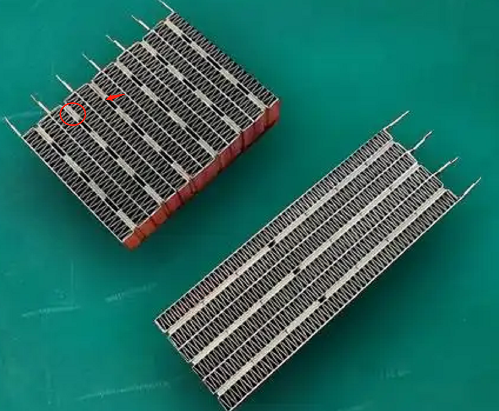
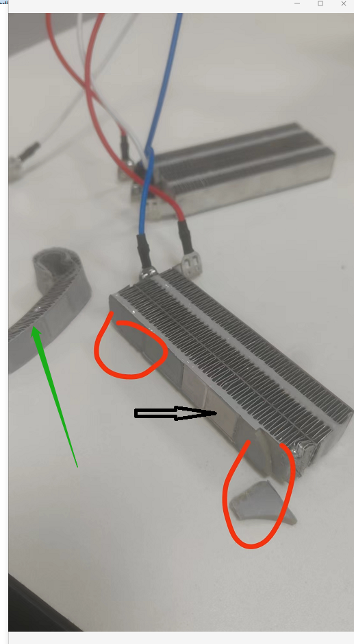
figure 1
figure 2

How is the creepage distance of the functional insulation at the location of the red circle in Figure 1 determined?
We all know that NOTE 1 of TABLE 18 section has the following requirements.
NOTE 1 For PTC heating elements, the creepage distances over the surface of the PTC material need not be greater than the associated clearance for working voltages less than 250 V and for pollution degrees 1 and 2. However, the creepage distances between terminations are those specified in the table.
In the first case, the heating units are fixed by means of a conductive adhesive and a heat sink, with some gaps between the heating units, but all the gaps are filled with an insulating adhesive.
As shown in Fig. 2, the heatsinks connected to the fire wire and the heatsinks connected to the zero wire are functionally insulated by means of an insulating structure filled with adhesive, whereby the electrical gaps and creepage distances are formed by the upper surface of the insulating adhesive. Since the environment in which the PTC heating elements are located is of pollution class III, then NOTE 1 of the TABLE 18 section does not apply. Therefore, the requirement for creepage distance is 3.2 mm if it is determined according to the 250 V operating voltage, but of course, we need to use the interpolation method to calculate the creepage distance limit at the rated voltage. Usually, the gap between the two heat sinks is about 2.4mm, then its resulting creepage distance and electrical clearance is generally 2.4mm, the smarter approach is to raise the gap on the insulating adhesive, made into a curved projection, which lengthens the creepage distance and electrical clearance.

The second case, the heating unit through the conductive glue and heat sinks are fixed, leaving a certain gap between the heating unit, but the surface of the heating unit are attached to the insulating adhesive.
And the requirements of the first case is the same, just the middle of the gap if you increase the creepage distance of the problem. In fact, it is not difficult to think of, can be in the middle of the gap near the location of the heating unit to increase the glue, glue can not be laid flat on the side of the heating unit, need to be laid into a U-shaped. Of course, this process is more difficult to realize, not recommended.

In the third case, the heating unit is only fixed by the conductive glue and the heat sink for sticking, and there is a gap between multiple heating units. See Figure 1, the upper left corner of the component. There is no insulating glue attached between the heat generating units or on the surface.
The electrical gap is present in the gaps. What is in dispute here is how to determine the creepage distance. According to conventional logic, there is no creepage distance. According to the definition of creepage distance, creepage distance is in the surface of the insulating material trip, two heat sinks between the heating unit is not an insulating material, so its surface can not form a creepage distance path. Since no creepage distance can be formed, the prerequisite of clause 29.2.4 is not satisfied, and therefore there is no need to assess the creepage distance of functional insulation.

However, I personally still believe that we need to consider creepage distances, because the existence of creepage distances also takes into account the deposition of contaminants on the surface of a material, which can lead to short circuits. Here the PTC heating element generally work in Pollution degree 3, the surface must be for the accumulation of a lot of pollutants, pollutants, if too much, will lead to functional insulation short-circuit, resulting in appliances or power supply lines in the protective device action. This is in fact a less safe means, and the standard does not allow for the operation of protective devices in the supply line.

Similar Posts

  • Clause 3 – How to Understand the Definition of “all-pole disconnection”

    all-pole disconnection: disconnection of both supply conductors by a single initiating action or, for multi-phase appliances, disconnection of all supply conductors by a single initiating actionNOTE For multi-phase appliances, the neutral conductor is not considered to be a supply conductor. Single-phase power: An AC power system composed of one live wire and one neutral wire.​Three-phase…

  • ข้อ 3 – วิธีทำความเข้าใจคำจำกัดความของ “ไฟล์แนบประเภท X”

    ประการแรก คำจำกัดความนี้ใช้สำหรับสายไฟ ประการที่สอง ตามหมายเหตุ สายไฟสามารถรับได้จากผู้ผลิตหรือหน่วยงานบริการเท่านั้น ประการที่สาม มีการกล่าวถึงในที่นี้ว่าโครงสร้างของสายไฟนั้นง่ายต่อการเปลี่ยน จากหมายเหตุจะเข้าใจได้ว่าหากสายไฟนี้สามารถหาซื้อได้จากตลาดอุปกรณ์เสริมเครื่องใช้ไฟฟ้าภายในบ้านทั่วไป สายไฟของหม้อหุงข้าวที่แสดงในภาพตัวอย่างข้างต้น จริงๆ แล้วไม่ใช่ของสายไฟที่กล่าวถึงที่นี่ ในที่สุดสายไฟก็อาจมีส่วนหนึ่งของเครื่องด้วย อุปกรณ์แนบ Type X จะต้องเปลี่ยนได้ง่าย ดังแสดงในรูปด้านล่าง สายไฟเชื่อมต่อกับขั้วขั้ว วิธีการเชื่อมต่อนี้สามารถทำได้โดยใช้ไขควงปากแบนธรรมดา เป็นประเภทที่ติดตั้งง่าย จึงสามารถกำหนดเป็นเอกสารแนบ Type X ได้ ด้วยเหตุผลเดียวกัน หากการเชื่อมต่อสายไฟที่นี่เชื่อมต่อโดยใช้ขั้วต่อที่สะดวกและรวดเร็วก็สามารถกำหนดเป็นไฟล์แนบ Type X ได้ แต่โครงสร้างนี้ไม่ค่อยเห็น ให้อ้างอิงถึงประโยคแรกของส่วนที่ 26.2 “ยกเว้นเครื่องใช้ไฟฟ้าที่มีซอฟต์แวร์เตรียมพิเศษ เครื่องใช้ไฟฟ้าที่มีส่วนต่อพ่วงแบบ X และอุปกรณ์ที่เชื่อมต่อกับสายไฟประจำที่ จะต้องมีขั้วต่อสำหรับต่อโดยใช้หมุดเกลียว แป้นเกลียว หรืออุปกรณ์ที่คล้ายกัน เว้นแต่เช่นนั้น การเชื่อมต่อทำได้โดยการบัดกรี” ซึ่งหมายความว่าอนุญาตให้ใช้สกรู น็อต หรืออุปกรณ์เชื่อมต่อที่คล้ายกันเพื่อเชื่อมต่ออุปกรณ์แนบประเภท X ได้อย่างสมบูรณ์ ในทางกลับกัน โครงสร้างที่ใช้สกรู น็อต หรืออุปกรณ์เชื่อมต่อที่คล้ายกันเพื่อการเชื่อมต่อที่สมบูรณ์สามารถกำหนดเป็นสิ่งที่แนบมาแบบ X ได้ มีการกล่าวถึงการบัดกรีในที่นี้ด้วย ดังนั้นเราจึงมีเหตุผลที่เชื่อได้ว่าการบัดกรีแข็งเป็นวิธีการเชื่อมต่อที่ใช้โดยไฟล์แนบ Type…

  • ข้อ 3 – วิธีทำความเข้าใจคำจำกัดความของ “กระแสไฟฟ้าที่ได้รับการจัดอันดับ”

    หมายเหตุ หากไม่มีการกำหนดกระแสไฟฟ้าให้กับเครื่องใช้ไฟฟ้า กระแสไฟที่กำหนดจะเป็น– สำหรับเครื่องทำความร้อน กระแสไฟฟ้าคำนวณจากกำลังไฟเข้าที่กำหนดและแรงดันไฟฟ้าที่กำหนด– สำหรับเครื่องใช้ไฟฟ้าที่ทำงานด้วยมอเตอร์และเครื่องใช้ไฟฟ้าแบบรวม กระแสไฟฟ้าที่วัดได้เมื่อจ่ายเครื่องใช้ไฟฟ้าด้วยแรงดันไฟฟ้าที่กำหนดและทำงานภายใต้การทำงานปกติ สิ่งนี้สอดคล้องกับกำลังไฟฟ้าเข้าที่กำหนด และถูกกำหนดในลักษณะเดียวกับกำลังไฟฟ้าเข้าที่กำหนด หมายเหตุแรกของข้อนี้ เครื่องทำความร้อน เนื่องจากมีเพียงองค์ประกอบความร้อนไฟฟ้าเพื่อให้ความร้อนเท่านั้น องค์ประกอบความร้อนนี้โดยพื้นฐานแล้วจะมีโหลดความต้านทานเพียงอย่างเดียว ดังนั้นคุณจึงสามารถปฏิบัติตามวิธีการคำนวณทางคณิตศาสตร์ได้โดยตรง เนื่องจากกระแสจะเท่ากับกำลังไฟฟ้าเข้าที่หาร โดยแรงดันไฟฟ้าที่กำหนด (P = U/I) หมายเหตุประการที่สอง เนื่องจากผลิตภัณฑ์ไม่ใช่โหลดที่มีความต้านทานเพียงอย่างเดียว ดังนั้นตามสูตรการคำนวณ P = U/I จึงไม่ได้ให้ผลลัพธ์ที่ถูกต้อง มีเพียงการทดสอบเพื่อให้ได้ค่าปัจจุบันเท่านั้นโดยทั่วไปมีบ้างเครื่องใช้ไฟฟ้าที่ทำงานด้วยมอเตอร์ มีป้ายระบุพิกัดกระแสในป้ายพิกัด เช่น ตู้เย็น เครื่องปรับอากาศส่วนใหญ่จะมีทั้งกำลังไฟเข้าพิกัดและกระแสไฟพิกัดบนป้ายพิกัด ฉลากจัดอันดับสำหรับตู้เย็น ป้ายเรตติ้งเครื่องปรับอากาศ rating label for air conditioner

  • ข้อ 3 – วิธีทำความเข้าใจคำจำกัดความของ “อุปกรณ์คลาส 0I”

    เครื่องใช้ไฟฟ้ามีขั้วต่อสำหรับเชื่อมต่อตัวนำป้องกันภายนอก (ตัวนำสายดินป้องกัน) แต่ไม่มีสายไฟสำหรับเชื่อมต่อเครื่องใช้ไฟฟ้ากับตัวนำป้องกันในการเดินสายไฟแบบตายตัว เครื่องใช้ไฟฟ้าอาจมีสายไฟหรือโครงสร้างด้านในเพื่อส่งสัญญาณความต่อเนื่องของดิน ในญี่ปุ่น มีปลั๊กสำหรับอุปกรณ์คลาส 0I โดยเฉพาะ ดังที่แสดงด้านล่าง จากสิ่งที่ฉันเข้าใจ ปัจจุบัน มีเพียงญี่ปุ่นเท่านั้นที่ใช้อุปกรณ์คลาส 0I โดยปกติแล้วสายไฟจะมีสายดิน แต่การต่อลงดินไม่ได้กระทำโดยหมุดสายดินในปลั๊ก แต่จะใช้เครื่องมือในการเชื่อมต่อขั้วต่อหรือวงแหวนสายดินที่แยกจากกันเพื่อให้การต่อสายดินมีประสิทธิภาพ นอกจากนี้ ยังมีขั้วต่อสายดินบนอุปกรณ์ด้วย ก่อนการติดตั้ง ขั้วต่อนี้ไม่ได้เชื่อมต่อกับสายไฟภายนอกใดๆ และโดยปกติจะเชื่อมต่อระหว่างการใช้งานและการติดตั้ง From what I understand, at present, only Japan uses class 0I appliances. Usually, the supply cord have an earthing wire, but the earthing is not done by the earthing pin in the plug. Instead,…

  • Clause 3 – How to understand the definition of “non-self-resetting thermal cut-out”

    non-self-resetting-thermal cut-out: thermal cut-out that requires a manual operation for resetting, or replacement of a part, in order to restore the current.NOTE Manual operation includes disconnection of the appliance from the supply mains. The thermal cut-out is equipped with a temperature-sensitive component, typically a bimetallic strip or a thermistor, which reacts to heat. As the…

  • Clause 3 – How to understand the definition of “temperature limiter”

    temperature limiter: temperature-sensing device, the operating temperature of which may be either fixed or adjustable and which during normal operation operates by opening or closing a circuit when the temperature of the controlled part reaches a pre-determined value.Note 1 to entry: A temperature limiter does not make the reverse operation during the normal duty cycle…