Clause 3 – How to understand the definition of “detachable part”

detachable part: part that can be removed or opened without the aid of a tool, a part that is removed or opened in accordance with the instructions for use, even if a tool is needed for removal, or a part that does not fulfil the test of 22.11.
NOTE 1 If for installation purposes a part has to be removed, this part is not considered to be detachable even if the instructions state that it is to be removed.
NOTE 2 Components that can be removed without the aid of a tool are considered to be detachable parts.

The definition of this concept is mainly for the judgment of clause 8 and clause 20, and may also be used for the judgment of other chapters. Whether any part of an appliance can be removed cannot be judged by a certain arbitrary or subjective principle. Therefore, here, the standard stipulates three principles to determine whether the parts of the appliance can be removed. The first principle is the parts that can be removed without using tools; the second principle is the parts that can be removed or opened according to the instructions. If the instructions require the use of tools to operate, they can also be considered detachable; the third principle is the parts that cannot withstand the test of clause 22.11. This principle is actually a set of experimental methods to determine whether a part is firmly fixed; different people have different strengths and use different tools. For the same part, some people can remove it without the help of tools, while others cannot remove it due to lack of strength; therefore, a unified method is fixed here for execution. The clause needs to be understood together with the non-detachable part clause. From the literal meaning of the noun alone, it can be understood that a part is either a detachable part or a non-detachable part. However, analyzing the definition of the clause, it is not an either-or relationship here. The difference is that in the definition of detachable parts, there is an additional clause “parts that are removed or opened according to the instructions (even if tools are required to remove them)”, that is, if a part meets this additional condition, it can be judged as both a detachable part and a non-detachable part. For example, the instructions of some air purifiers will tell users how to use a screwdriver to remove the outer shell to replace the internal filter, and some floor-standing fans will also tell users in the instructions how to use a screwdriver to remove the mesh cover, and then remove the fan blades to complete the cleaning work. These disassembled parts are detachable parts.

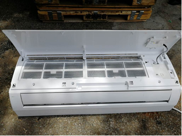
When installing the indoor unit of a split wall-mounted air conditioner, you need to open the upper cover and remove the junction box cover. The junction box cover here needs to be removed during installation and reset after installation. The cover is not considered a detachable part. As shown below:
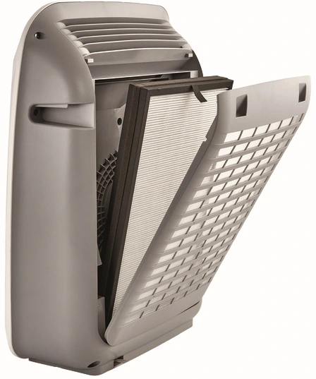
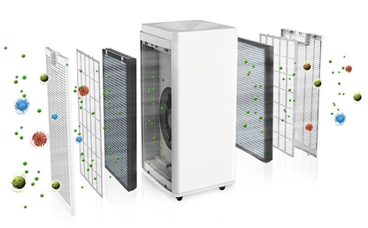
In order to facilitate the updating of filters and filter elements, the air purifier products are designed to fix the filters and filter covers with a snap structure, and the replaceable filters and filter covers are detachable parts. As shown below:
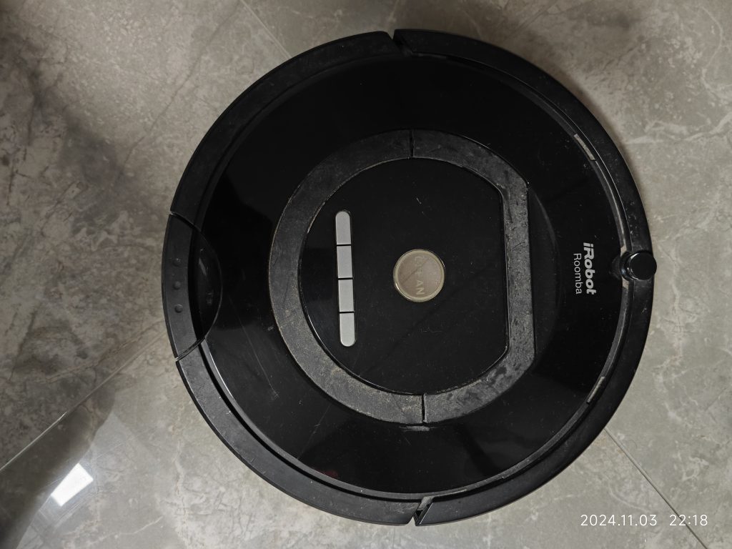
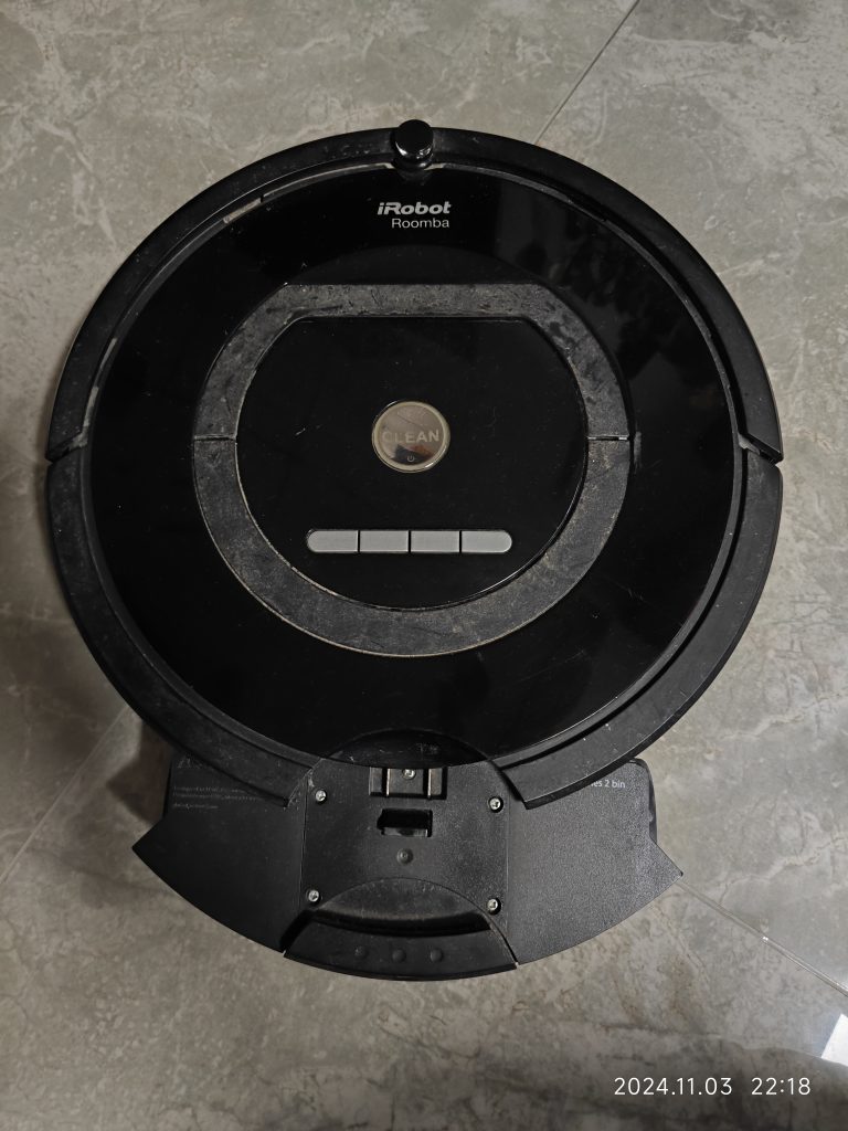
The filter of the sweeping robot shown in the figure below is a detachable part
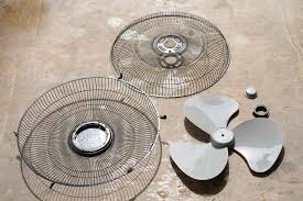
fan grille for floor-standing fan shown as below:
Similar Posts

  • 第 3 項 – 「タイプ Y アタッチメント」の定義の理解方法

    タイプ Y アタッチメント: 製造元、そのサービス代理店、または同様の資格を持つ担当者が交換を行うための電源コードの取り付け方法。 次の 2 つの写真に示すように、アプライアンスの底部にあるカバーを取り外すと、コード クランプと内部電源コード コネクタが見えます。底部カバーの取り外しは比較的簡単ですが、電源コードが同様のニップルコネクタに接続されているか、機械的に固定されている場合は、電源コードを再接続するために専門の工具や破壊が必要となり、電源コードの交換が困難になります。この構造をタイプ Y アタッチメントとして定義する方が合理的です。 As shown in the following two pictures, after removing the cover at the bottom of the appliance, you can see the cord clamp and the internal supply cord connector. Removing the bottom cover is relatively easy, but if the power cord is connected with…

  • How are the creepage distances and electrical clearances of PTC heating element surfaces determined?

    We are discussing here the second structure of the PTC heating element, PTC heating element structure please refer to the explanation of its definition. How is the creepage distance of the functional insulation at the location of the red circle in Figure 1 determined? We all know that NOTE 1 of TABLE 18 section has…

  • Clause 3 – How to understand the definition of “non-self-resetting thermal cut-out”

    non-self-resetting-thermal cut-out: thermal cut-out that requires a manual operation for resetting, or replacement of a part, in order to restore the current.NOTE Manual operation includes disconnection of the appliance from the supply mains. The thermal cut-out is equipped with a temperature-sensitive component, typically a bimetallic strip or a thermistor, which reacts to heat. As the…

  • Clause 3 – How to understand the definition of “stationary appliance”

    stationary appliance: fixed appliance or an appliance which is not a portable appliance. Stationary appliance includes fixed appliance and not a portable appliance. The characteristic of a stationary appliance is that once it is put into use, it will be placed in a fixed position. At the same time, the position of the appliances will…

  • 第3項「機能絶縁」の定義の見方

    機能的絶縁: 電位の異なる導電性部分間の絶縁であり、機器が適切に機能するためにのみ必要です。 下の図は典型的な機能絶縁の図です。PCB の銅レール層の図に示されているように、ラベルの茶色の部分は電源活線 (電流ヒューズ間に接続されている 2 つの茶色の位置)、青色の部分です。接続は電力線の中性線であり、活線であり、中性線には 2 つの線の間に電圧差があるため、選択した銅線レールの青色の部分と選択した銅線レールの茶色の部分の間の最短距離になります。レール、つまり機能絶縁体です。実際、通常の動作では、下の写真の回路基板、銅レール上の電圧は多くの場所で同じではないため、機能絶縁の形成により、読者は動作電圧によって独自の回路分析を行うことができます。各部分。 AC 非同期モーターの一般的な巻線接続図は次の図のようになります。図のコンデンサが動作しているとき、コンデンサの両端の電圧は通常、製品の定格電圧よりも高くなります。たとえば、定格電圧が 220V の場合、動作中にマルチメータで測定されるコンデンサの両端の電圧は通常 300V を超えます。このとき、コンデンサの両端間の機能絶縁を評価する場合、300V以上の使用電圧を基準に評価する必要がありますが、実際にはコンデンサ自体の機能絶縁は一般的には可能ではありません。コンデンサの端子がコンデンサのケース内に封入されているため測定されます。測定できる箇所はコンデンサの2本のリード線の端子台です。 下図に示すように、端子台には左側に活線が接続され、右側に中性線が接続されています。赤い線の位置は機能絶縁体の沿面距離です(クリアランスもここで決定できます)。 下の図に示されているキャリパーの測定値は、PCB 上のアダプターの入力のライブ銅線と中性銅線の間の機能絶縁を表しています。 As shown in the figure below, the terminal block has the live wire connected on the left and the neutral wire connected on the right. The position of the red line is the creepage distance of the…

  • 第 3 項 – 「タイプ X アタッチメント」の定義の理解方法

    タイプXアタッチメント:電源コードの交換が容易な取付方法エントリへの注記 1: 電源コードは特別に用意され、製造元またはそのサービス代理店からのみ入手できる場合があります。特別に用意されたコードには器具の一部が含まれる場合があります。 まず、この定義は電源コード用です。次に、注記によると、コードは製造元またはそのサービス代理店からのみ入手できます。第三に、電源コードの交換が容易な構造であることが挙げられる。注記から、このコードが一般の家電付属品市場で購入できる場合、炊飯器の供給コードであることがわかります 上の図の例に示されているものは、実際にはここで言及されている電源コードに属しません。最後に、電源コードもアプライアンスの一部である場合があります。 Type X のアタッチメントは簡単に交換できる必要があります。以下の図に示すように、 電源コードは極性端子に接続されています。この接続方法は通常のマイナスドライバーで完了します。取り付けが容易なタイプですので、タイプXアタッチメントとして定義できます。同様の理由で、ここでの電源コードの接続が便利でクイックなコネクタを使用して接続されている場合は、タイプ X アタッチメントとして定義することもできますが、この構造はほとんど見られません。セクション 26.2 の最初の文を参照してください。「特別な準備ソフトウェアを備えた機器を除き、タイプ X の取り付け接続を備えた機器および固定配線に接続された機器には、ネジ、ナット、または同様の装置による接続用の端子が提供されなければなりません。接続はハンダ付けで行います。」これは、タイプ X の取り付け接続を完了するために、ネジ、ナット、または同様の接続デバイスを使用できることを意味します。逆に、ネジ、ナット、または同様の接続デバイスを使用して接続を完了する構造は、タイプ X アタッチメントとして定義できます。ここではろう付けについても言及されているので、ろう付けもタイプ X アタッチメントで使用される接続方法であると考える理由がありますが、個人的にはろう付けは簡単な接続方法ではないため、タイプ X アタッチメントとはみなせないと考えています。ろう付けを伴う場合は、ろう付けよりも簡単なはんだ付けを検討しますが、はんだ付けも容易ではないと思いますので、Type Xアタッチメント接続と判断することはお勧めできません。タイプXの付属品は現在では非常に珍しいと言わざるを得ません。技術の向上と材料の最適化により、電源コードの損傷はほとんど発生しなくなり、たとえ電源コードが損傷したとしても、一般のユーザーが自分で修理や交換することは困難です。ほとんどの電気製品はタイプ Y の取り付け構造を採用しています。標準でタイプ X の取り付けを定義したとき、後進技術により多くの電源コードが損傷したため、この安全規則が規定されました。 It has to be said that type X attachment is very rare now. Due to the improvement of technology and the optimization of materials, the damage of…